


Section 4
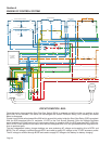
ENGINE DC CONTROL SYSTEM
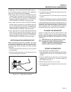
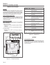
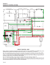
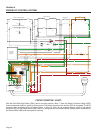
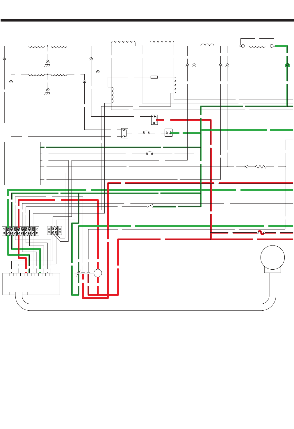
CIRCUIT CONDITION - REST:
Battery voltage is supplied to components of the control system from the unit BATTERY via the RED battery cable
connected to the contacts of the starter contactor (SC), wire 13, a 10 Amp fuse (F1), and Wire 15.
Wire 13 is unfused battery supply voltage and is connected to the contacts of the Starter Contactor Relay (SCR).
Wire 15 12 VDC fused battery supply voltage is supplied to the SCR coil, it goes through the coil and comes out
as wire 17 12 VDC, wire 17 is connected to the Start-Run-Stop switch (SW1) and is held open to ground. No cur-
rent flows through the circuit and the SCR is de-energized.
Wire 15 12 VDC fused battery supply voltage is supplied to SW1 and is held open to Wire 167.
Wire 15 12 VDC fused battery supply voltage is supplied to the Start-Stop Relay (SSR) it goes through the coil
and comes out as wire 229 12 VDC, wire 229 is connected to the printed circuit board and is held open to ground.
No current flows through the circuit and the SSR is de-energized.
Page 20
VOLTAGE
ELECTRONIC
REGULATOR
11S
162
0
6
44S
4
6
5
4
3
2
1
BCR2
77A
15
66A
564
1012
SSR
9
RESET
RESET
TEST
TEST
18
IM2
SP2
IM1
SP1
PRINTED CIRCUIT
BOARD
CONTROL
12 1011 9 278 6 45 3
J2
1
J1
15B
83
TR1
0
167
TR2
86
229
44S
11S
ACTUATOR
GOVERNOR
0 0 44C2211C22
C.B.
0000
222222
44D11D44B
11B
11B
0
11A44A
22
20A
C.B.
20A30A
C.B.
30A
C.B.
30A
C.B.
50A
C.B.
30A
C.B.
FIELD
0
167
SW1
BATTERY CHARGE WINDING
55A
10A BATTERY CHARGE WINDING
77
55
11S
112244
44S
66
77A 66A
62 4 0
C1-12C1-11C1-7C1-6C1-1
C1-2
C1-4
C1-9
C1-8
C1-10
C1-5
C1-3
77
66
BCR1
13A
CB2
83
167
229
15B
0
86
SW2
FSS
LOP
0
15
17
0
17
15
0
0
86
14
C2-8
C2-3
C2-4
C2-10
C2-5
C2-7
C2-1
C2-2
15
C2-12
0
0
16
SC
BATTERY
BLACK
RED
SC
SM
12V
CB1
15A 0
C2-6
C2-11
C2-9
13
13
F1
SCR
22914
15B
18
0
15
15 15
0
0
0
167
15
15
86
0
14
17
18
13
13
16
14
14
14
14
86
13
15
15
1515
15
15
15
15
14
18 18
167167
8686
4
4
162
11S
44S
22
11
0
44
11
0
22
44
11
0
22
44
11
0
22
4444
77A
77
66A
66
77
0
2
2
2
6
6
6
11S 4 044S
RED
BLK
BLK
83 0
0
00
0
229
15B
15
15
15
0
17
17
4
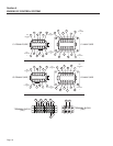
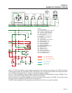
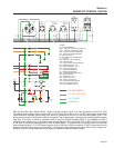
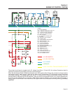
SCR - STARTER CONTACTOR RELAY
SW1 - START-RUN-STOP SWITCH
SSR - START / STOP RELAY
SP2 - SPARK PLUG, CYL. 2
SP1 - SPARK PLUG, CYL. 1
SM - STARTER MOTOR
SC - STARTER CONTACTOR
R1 - 25 OHM, 25W RESISTOR
IM2 - IGNITION MODULE, CYL. 2
FSS - FUEL SHUT OFF SOLENOID
CB1 - 10AMP AUTO RESET BREAKER
LOP - LOW OIL PRESSURE
IM1 - IGNITION MODULE, CYL. 1
GND - GROUND BAR
F1 - 10A FUSE
D2, D3 - ENGINE SHUTDOWN DIODE
BA - BRUSH ASSEMBLY
LEGEND
120/240V
50A
TWISTLOK TWISTLOK
120V/30A
TWISTLOK
120V/30A
DUPLEX
120V 120V
GFCI
30A
120/240V
POWER WINDING
DPE WINDING
I.C.T.
I.C.T.
I.C.
R1D1
TB1
TB2
D2
D3
12Vdc
BA
CB2 - 5AMP AUTO RESET BREAKER
D1 - 600V 12A DIODE
BCR2 - BATTERY CHARGE RECTIFIER
BCR1 - BATTERY CHARGE RECTIFIER, 10A
I.C.T. - IDLE CONTROL TRANSFORMER
SW2 - IDLE CONTROL SWITCH
TB1, TB2 - TERMINAL BLOCK
13
14
13
= 12 VDC SUPPLY
= 12 VDC CONTROL
= AC POWER
= GROUND