


Section 6
DIAGNOSTIC TESTS
Page 41
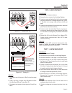
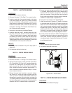
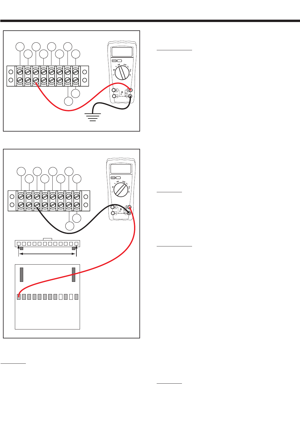
TERMINAL
BLOCK
(TB1)
12.00
86 15B
167
BLK
0 229
83
BLK
TR2
TR1
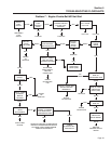
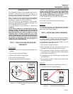
Figure 6-5. – Testing Wire 15B
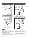
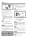
TB1
J2 HARNESS CONNECTOR
00.00
86 15B
167
BLK
0 229
83
BLK
TR2
TR1
J2-1 J2-12
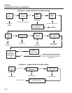
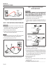
MAKE SURE THE TEST
PROBE CONNECTOR IS
MAKING CONTACT
WITH THE CONNECTOR.
DOUBLE CHECK TO
MAKE SURE THAT THE
TIP IS SHARP.
Figure 6-6. – Testing J2-1
RESULTS:
1. If the stepper motor fails any part of Step 5 replace the stepper
motor.
2. If Step 7 fails repair or replace Wire 15B between the Start-
Run-Stop Relay (SSR) and Terminal Block TB1.
3. If the stepper motor passes all steps replace the Printed Circuit
Board.
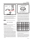
TEST 6 - WIRE CONTINUITY
PROCEDURE:
1. Set a Voltmeter to measure resistance.
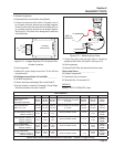
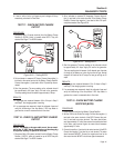
2. Remove the six pin connector from the Voltage Regulator.
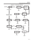
3. Connect one meter test lead to Wire 0 in the six pin connector
previously removed from the Voltage Regulator. See Figure 6-
11. Be careful not to damage the pin connectors with the test
leads.
3. Connect the other test lead to the ground terminal in the control
panel. The meter should read continuity.
4. Connect one meter test lead to Wire 162 in the six pin connec
-
tor previously removed from the Voltage Regulator. See Figure
6-11. Be careful not to damage the pin connectors with the test
leads.
5. Remove Wire 162 from the Excitation Circuit Breaker (CB1).
Connect the other meter test lead to Wire 162. The meter
should read continuity.
RESULTS:
If continuity was NOT measured across each wire,
repair or replace the wires as needed. If continuity
WAS measured refer back to flow chart.
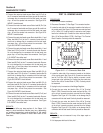
TEST 7 - CHECK FIELD BOOST
PROCEDURE:
1. Set VOM to measure DC voltage.
2. Disconnect the six pin connector from the Voltage Regulator.
3. Disconnect Connector C1. See Page 17 for connector location.
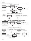
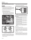
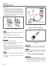
4. Disconnect Wire 16 from the Starter Contactor Relay (SCR).
See Figure 6-13. This will cause the unit not to crank when
placed in the Start position.
5. Connect the positive meter test lead to Wire 4 at the diode
(D1), Wire 4 is soldered to the diode. See Figure 6-14. Connect
the negative meter test lead to the ground terminal.
6. Set the Start-Run-Stop Switch (SW1) to START. Measure the
DC voltage. It should read approximately 12 VDC.
7. Reconnect the Six Pin connector to the Voltage Regulator,
Reconnect the C1 connector, and reconnect Wire 16 to the
Starter Contactor Relay.
RESULTS:
1. If 12 VDC was measured in Step 5 the field boost circuit is
working refer back to the flow chart.
2. If field boost voltage was not measured refer back to the flow
chart.