


Page 47
Section 6
DIAGNOSTIC TESTS
2. If load is within limits, but frequency and voltage still drop
excessively, refer back to Flow Chart.
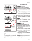
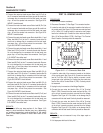
TEST 17 - CHECK BATTERY CHARGE
OUTPUT
PROCEDURE:
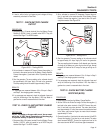
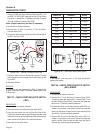
1. Disconnect Wire 15 (center terminal) from the Battery Charge
Rectifier 2 (BCR2), which is located under BCR1. They are
stacked. See Page 17 for BCR2 location.
66A
15
BCR2
77A
15
2.0 a
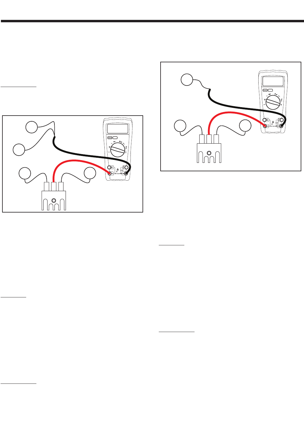
Figure 6-23. – Testing BCR2
2. Set a voltmeter to measure DC Amps. Connect the positive (+)
test lead to the center terminal of the Battery Charge Rectifier.
Connect the negative (-) test lead to Wire 15 previously discon-
nected.
3. Start the generator. The amp reading on the voltmeter should
be approximately 0.6 Amps. Apply full load to the generator.
The amp reading should increase to approximately 2 Amps.
RESULTS:
1. If amperage was measured between 0.6 to 2 Amps in Step 2
and Step 3, the charging system is working.
2. If no amperage was measured, check the voltmeter fuses and
verify the functioning of the Amp Meter. If DC Amp Meter is
good and no current is measured refer to flow chart.
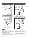
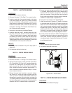
TEST 18 - CHECK 10 AMP BATTERY CHARGE
OUTPUT
PROCEDURE:
NOTE: The battery charge cable must be connect-
ed to the 12 VDC panel receptacle and be charging
a separate battery to perform this test.
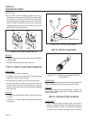
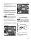
1. Disconnect Wire 13A (center terminal) from the Battery Charge
Rectifier 1 (BCR1), which is located on top of BCR2 they are
stacked. See Page 17 for BCR1 location.
2. Set a voltmeter to measure DC Amperage. Connect the posi-
tive (+) test lead to the center terminal of the Battery Charge
Rectifier. Connect the negative (-) test lead to Wire 13A previ-
ously disconnected. See Figure 6-24.
66
BCR1
77
13A
5.0 a
Figure 6-24. – Testing BCR1
3. Start the generator. The amp reading on the voltmeter should
be approximately 0.2 Amps. Apply full load to the generator.
The amp reading should increase. It will depend upon the state
of charge of the battery as to how high current will get. Normal
ranges at full load can be 3-7 amps, but can get as high as 10
amps.
RESULTS:
1. If amperage was measured between 0.2 to 10 Amps in Step 2
and Step 3, the charging system is working.
2. If no amperage was measured, check the voltmeter fuses and
verify the functioning of the Amp Meter. If DC Amp Meter is
good and no current is measured refer to flow chart.
TEST 19 - CHECK BATTERY CHARGE
RECTIFIER (BCR2)
PROCEDURE:
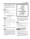
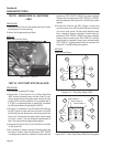
1. Disconnect all wires from the Battery Charge Rectifier.
2. Set the VOM to the Diode Test range. Connect the negative (-)
test lead to the center terminal of the BCR. Connect the posi
-
tive (+) test lead to an outer terminal. The meter should mea-
sure approximately 0.5 volts. Now connect the positive test lead
to the other outer terminal. Again, the meter should measure
approximately 0.5 volts.
3. Connect the positive (+) test lead to the center terminal of the BCR.
Connect the negative (-) test lead to an outer terminal. The meter
should measure INFINITY. Connect the negative test lead to the
other outer terminal. INFINITY should once again be measured.