


Section 6
DIAGNOSTIC TESTS
Page 49
measure at the battery terminals during cranking. If battery
voltage is below 11 volts DC, recharge/replace battery. If bat-
tery or cables are still suspected, connect an alternate battery
and cables to the generator and retest.
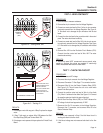
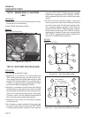
2. Use a battery hydrometer to test the battery for (a) state of
charge and (b) condition. Follow the hydrometer manufacturer's
instructions carefully.
RESULTS:
1. Clean battery posts and cables as necessary. Make sure bat-
tery cables are tight.
2. Recharge the battery, if necessary.
3. Replace the battery, if necessary.
4. If battery is good, but engine will not crank, refer back to Flow
Charts.
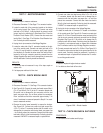
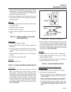
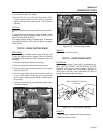
TEST 23 - CHECK VOLTAGE AT STARTER
CONTACTOR (SC)
PROCEDURE:
1. Set voltmeter to measure DC voltage.
2. Disconnect Wire 16 from the Starter Contactor located on the
Starter motor.
3. Connect the positive meter test lead to Wire 16 previous
-
ly removed. Connect the negative meter test lead to frame
Ground.
4. Place the Start-Run-Stop Switch to Start. 12 VDC should be
measured.
5. Reconnect Wire 16 to the Starter Motor.
RESULTS:
Refer back to flow chart.
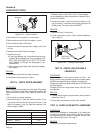
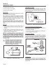
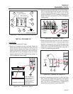
TEST 24 - CHECK STARTER CONTACTOR (SC)
PROCEDURE:
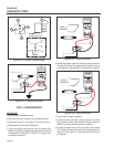
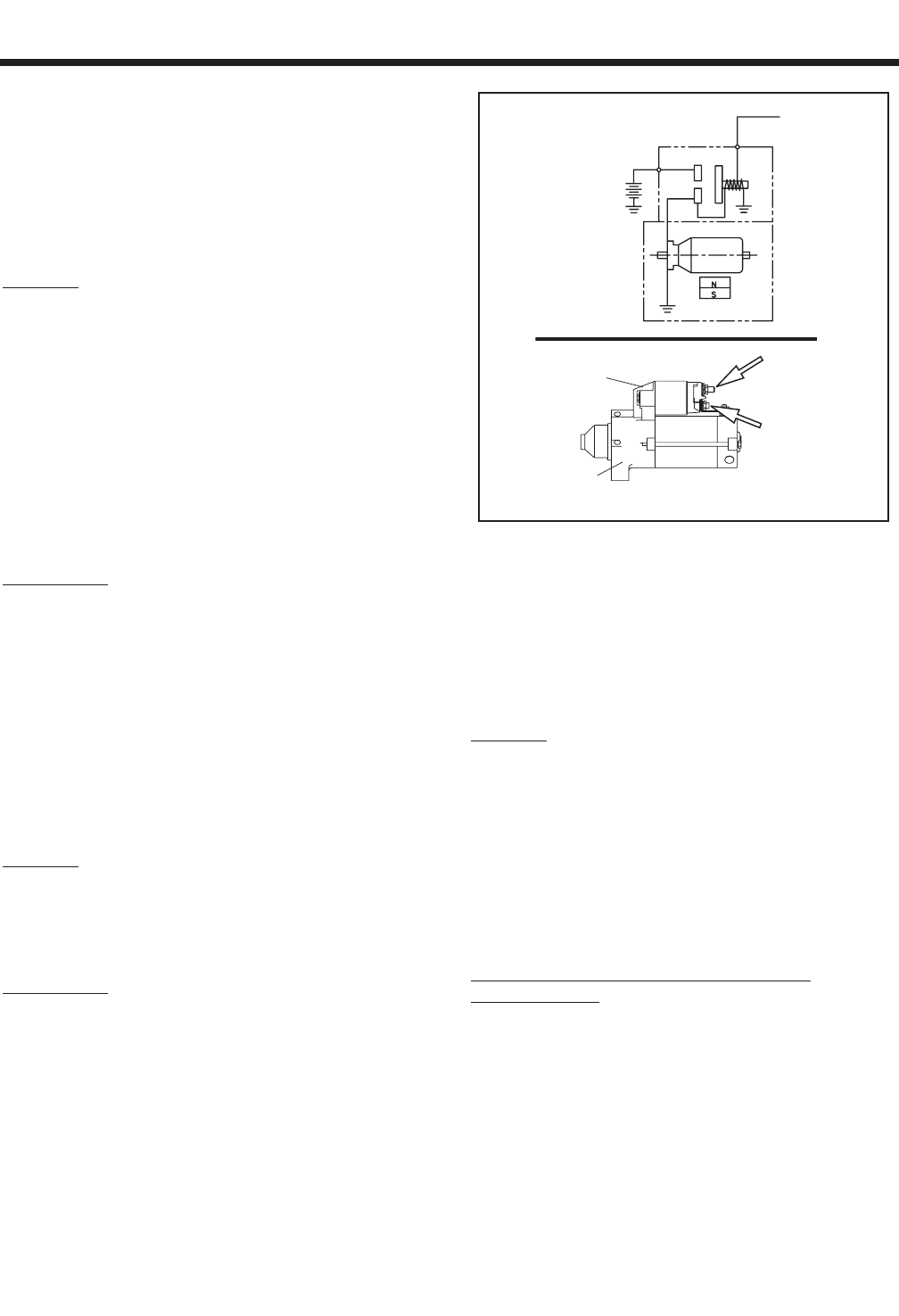
1. Carefully inspect the starter motor cable that runs from the
Battery to the Starter Motor. Cable connections should be
clean and tight. If connections are dirty or corroded, remove
cable and clean cable terminals and studs. Replace any cable
that is defective or badly corroded. Set the voltmeter to mea-
sure DC voltage. Connect the positive (+) meter test lead to
the Starter Contactor stud that the battery cable is connected
to. Connect the negative (-) meter test lead to a clean frame
ground. Battery voltage should be measured (see Figure 6-28,
STEP 1 TEST POINT).
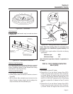
CONNECTING
DIAGRAM
BATTERY
12V
STARTER
SWITCH
PERMANENT MAGNET
30
50
16
STARTER
CONTACTOR
STARTER
MOTOR
STEP 2
TEST POINT
STEP 1
TEST POINT
Figure 6-28. – The Starter Contactor (SC)
2. Set the voltmeter to measure DC voltage. Connect the positive
(+) meter test lead to the Starter Contactor stud that has the
small jumper wire connected to the Starter. Connect the nega-
tive (-) meter test lead to a clean frame ground. Set the Start-
Stop Switch to START. Battery voltage should be measured
(see Figure 6-28, STEP 2 TEST POINT).
RESULTS:
1. If battery voltage was not measured in Step 1, repeat Test 22.
2 If battery voltage was measured in Step 1, but not in Step 2,
replace the Starter Contactor.
4. If battery voltage was measured in Step 2 but the engine still
does not crank, refer back to the Flow Chart.
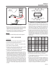
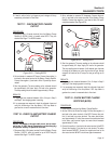
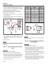
TEST 25 - CHECK STARTER MOTOR
CONDITIONS AFFECTING STARTER MOTOR
PERFORMANCE:
1. A binding or seizing condition in the Starter Motor bearings.
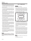
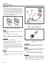
2. A shorted, open or grounded armature.
a. Shorted, armature (wire insulation worn and
wires touching one another). Will be indicated by
low or no RPM.
b. Open armature (wire broken) will be indicated
by low or no RPM and excessive current draw.
c. Grounded armature (wire insulation worn and
wire touching armature lamination or shaft). Will
be indicated by excessive current draw or no
RPM.