


PROCEDURE:
1. Set a voltmeter to measure resistance.
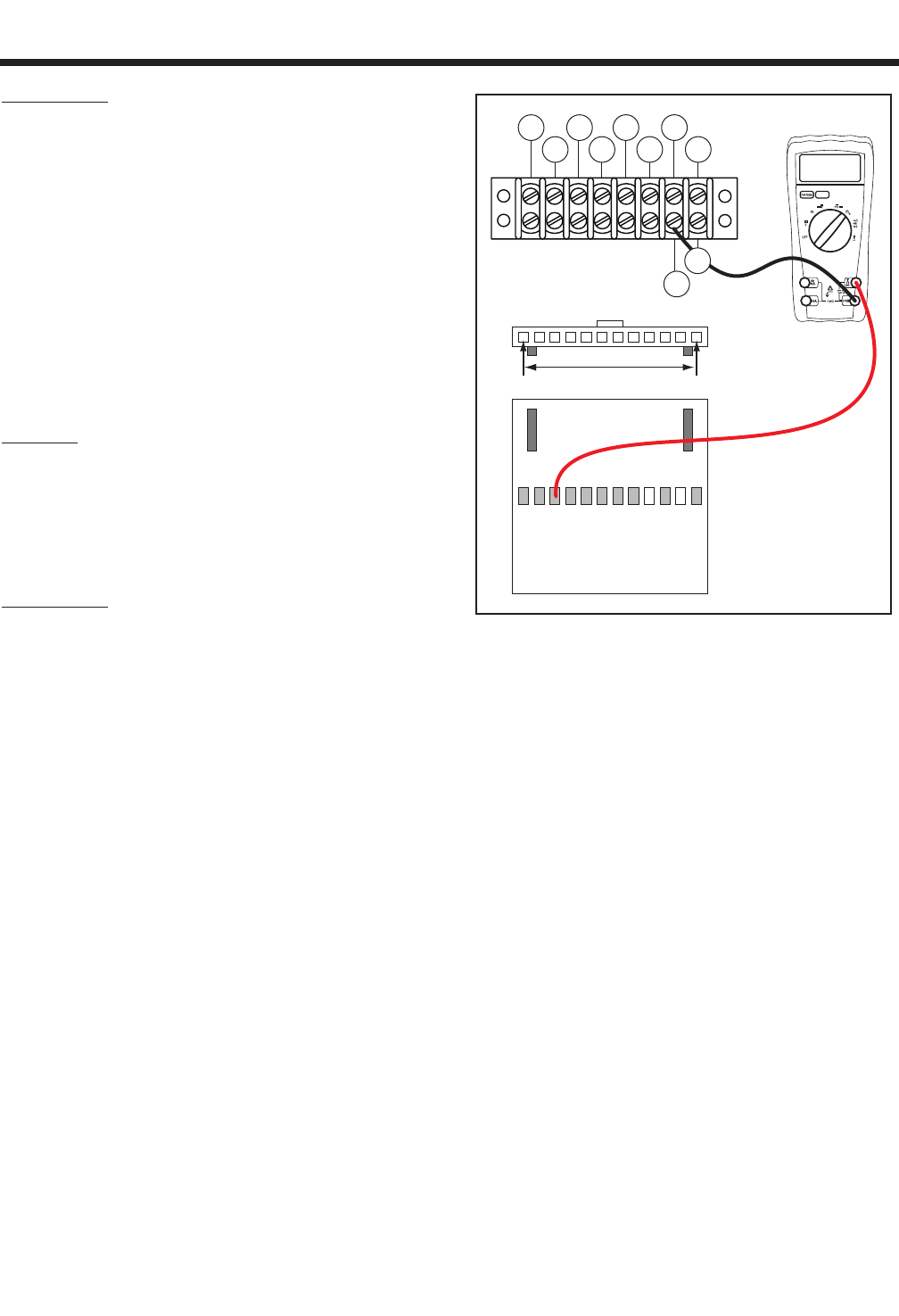
2. Disconnect the J2 connector from the printed circuit board.
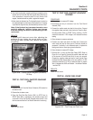
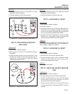
3. Connect one meter test lead to Wire TR2 at Terminal Block 1
(TB1). See Figure 6-62. Connect the other meter test lead to
pin location J2-6 on the J2 Connector previously removed. Be
careful not to damage the pin connectors with the test leads.
Continuity should be measured.
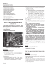
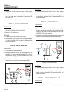
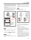
4. Connect one meter test lead to Wire TR1 at Terminal Block 1
(TB1). See Figure 6-63. Connect the other meter test lead to
pin location J2-3 on the J2 Connector previously removed. Be
careful not to damage the pin connectors with the test leads.
Continuity should be measured.
RESULTS:
1. Repair or replace defective wiring.
2. If wiring tests good replace printed circuit board.
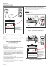
TEST 56 - CHOKE TEST
PROCEDURE:
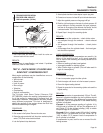
If the generator is surging it may have a carburetion
problem. A lean condition can cause erratic RPM.
Slowly pull the choke out to see if surging stops. If it
does stop, carburetion should be checked.
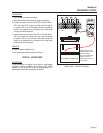
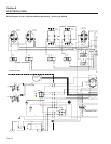
TB1
J2 HARNESS CONNECTOR
00.00
86 15B
167
BLK
0 229
83
BLK
TR2
TR1
J2-1 J2-12
MAKE SURE THE TEST
PROBE CONNECTOR IS
MAKING CONTACT
WITH THE CONNECTOR.
DOUBLE CHECK TO
MAKE SURE THAT THE
TIP IS SHARP.
Figure 6-63. – Check TR1 Wiring
Section 6
DIAGNOSTIC TESTS
Page 65