


Section 6
DIAGNOSTIC TESTS
Page 61
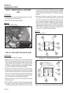
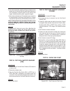
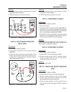
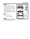
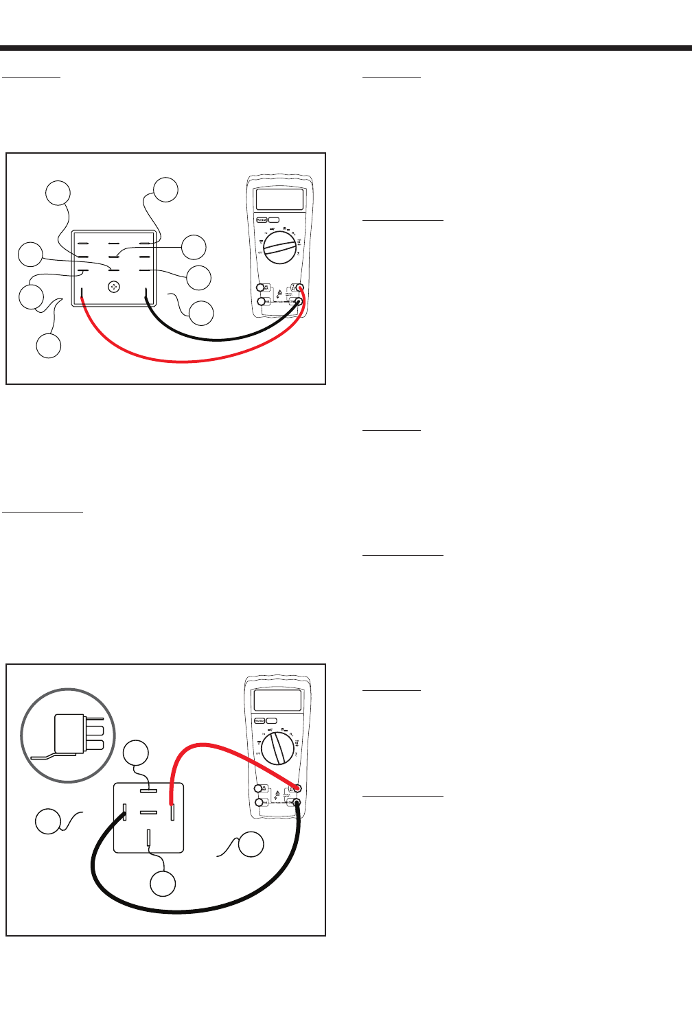
RESULTS:
1. If the SSR measures continuity or zero resistance it is shorted
to ground and should be replaced.
2. If the SSR resistance is correct refer to flow chart.
100 ohm
SSR
15B
1413
9 10 12
5
1 2
6
4
8
229
0
18
14
15
15
15
Figure 6-54. – Testing Start Stop Relay (SSR)
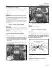
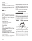
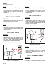
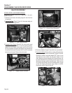
TEST 44 - TEST STARTER CONTACTOR
RELAY (SCR)
PROCEDURE:
1. Set a voltmeter to measure resistance.
2. Disconnect Wire 15 and Wire 17 from the Starter Contactor
Relay (SCR).
3. Connect one meter test lead to the terminal that Wire 15 was
removed from. Connect the other meter test lead to the ter
-
minal that Wire 17 was removed from. Resistance measured
should be approximately 75 ohms.
85
87a
30
86
SCR
87
16
15
17
13
75 ohms
Figure 6-55. – Testing Starter Contactor Relay (SCR)
RESULTS:
1. If the SCR measures continuity or zero resistance it is shorted
to ground and should be replaced.
2. If the SCR resistance is correct refer to flow chart.
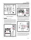
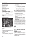
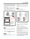
TEST 45 - CHECK WIRE 15 CIRCUIT
PROCEDURE:
1. Set a voltmeter to measure resistance.
2. Remove the Fuse (F1).
3. Disconnect all Wire 15’s from the Start Stop Relay (SSR), dis
-
connect Wire 15 from the Starter Contactor (SC), Disconnect
Wire 15 from the Start-Run-Stop Switch (SW1), and disconnect
Wire 15 from the Battery Charge Rectifier 2 (BCR2).
4. Remove Wire 15 from the fuse holder (F1). Connect one meter
test lead to wire 15 just removed. Connect the other meter test
lead to frame ground. INFINITY should be measured.
RESULTS:
If INFINITY was not measured a short on Wire 15 to
ground exists. Inspect each wire 15 for a shorted con-
dition. Repair or replace as needed.
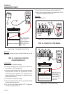
TEST 46 - CHECK WIRE 14 CIRCUIT
PROCEDURE:
1. Set a voltmeter to measure resistance.
2. Disconnect Wire 14 from the Start Stop relay (SSR).
3. Connect one meter test lead to Wire 14 previously removed.
Connect the other meter test lead to frame ground.
Approximately 38 ohms should be read.
RESULTS:
Refer back to flow chart.
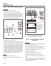
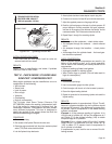
TEST 47 - CHECK FUEL SHUTOFF SOLENOID
(FSS)
PROCEDURE:
1. Set a voltmeter to measure resistance.
2. Disconnect the plug from the Fuel Shutoff Solenoid (FSS).
3. Connect one meter test lead to one pin on the FSS. Connect
the other meter test lead to the remaining pin in the FSS.
Approximately 38 ohms should be measured.
4. Connect one meter test lead to one pin on the FSS. Connect
the other meter test lead to frame ground. INFINITY should be
measured.