


Section 6
DIAGNOSTIC TESTS
Page 39
9. Shutdown the generator.
10. Reconnect Wire 2 to the Excitation Circuit Breaker.
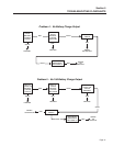
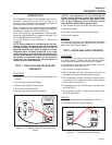
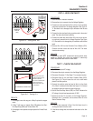
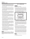
11. Connect one meter test lead to Wire 11S located in the six
pin connector previously removed from the Voltage Regulator.
Connect the other meter test lead to Wire 44S located in the six
pin connector previously removed from the Voltage Regulator.
See Figure 6-11. Be careful not to damage the pin connectors
with the test leads.
REGULATOR
VOLTAGE
PIN 6
PIN 5
PIN 4
PIN 3
PIN 2
PIN 1
44S
162
11S
0
4
6
Figure 6-11. - Voltage Regulator Pin Connector Wire
Number Locations
12. Start the generator.
13. Measure the output voltage across wires 11S and 44S and
record the results.
AC Voltage across Wires 11S and 44S= _________
14. Shutdown the generator.
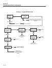
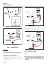
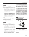
15. Remove the Jumper lead between Wire 14 and Diode D1.
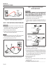
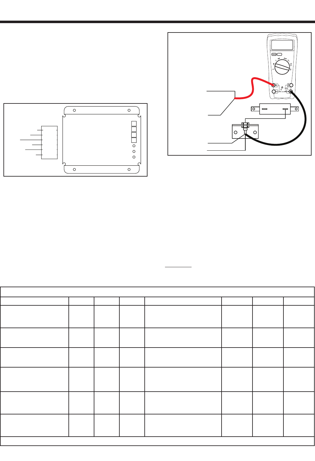
16. Set the voltmeter to measure DC amperage (10 Amp Range).
Switch the test leads on the meter if required.
D2
4
14
WIRE 14
REMOVED
14
4
R1
1.5 A
Figure 6-12. – Measuring Amp Draw
17. Connect the positive meter test lead to Wire 14. Connect the
negative test lead to Wire 4 at Diode D1. See Figure 6-12.
18. Start the generator.
19. Measure the DC Rotor Amp draw and record the results.
Rotor Amp Draw =________________
20. Shutdown the generator.
21. Reconnect the six pin connector.
22. Reconnect Wire 14 to the resistor R1.
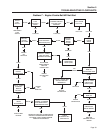
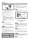
RESULTS:
Refer to "TEST 4 RESULTS" chart.
TEST 4 RESULTS
A B C D E F G
VOLTAGE RESULTS
WIRE 2 & 6
EXCITATION WINDING
ABOVE
60 VAC
ABOVE
60 VAC
BELOW
60 VAC
ZERO OR RESIDUAL VOLTAGE
(2-12 VAC)
BELOW
60 VAC
BELOW
60 VAC
ABOVE
60 VAC
VOLTAGE RESULTS
WIRE 11S & 44S
ABOVE
120 VAC
BELOW
120 VAC
ABOVE
120 VAC
ZERO OR RESIDUAL VOLTAGE
(2-12 VAC)
BELOW
120 VAC
BELOW
120 VAC
ABOVE
120 VAC
ROTOR AMP DRAW
12.5 kW (MODEL 004451-0)
(MODEL 004986-0)
1.8 A
± 20%
1.8 A
± 20%
1.8 A
± 20%
ZERO CURRENT DRAW 2.3 A
1.8 A
± 20%
ZERO
CURRENT
DRAW
ROTOR AMP DRAW
15 kW (MODEL 004582-0,1)
(MODEL 004987-0)
(MODEL 005209-0)
1.6 A
± 20%
1.6 A
± 20%
1.6 A
± 20%
ZERO CURRENT DRAW 2.1 A
1.6 A
± 20%
ZERO
CURRENT
DRAW
ROTOR AMP DRAW
15 kW (MODEL 004582-2)
(MODEL 004987-1)
0.96 A
± 20%
0.96 A
± 20%
0.96 A
± 20%
ZERO CURRENT DRAW 1.5 A
0.96 A
± 20%
ZERO
CURRENT
DRAW
ROTOR AMP DRAW
17.5 kW (MODEL 004583-0)
(MODEL 005308-0)
0.89 A
± 20%
0.89 A
± 20%
0.89 A
± 20%
ZERO CURRENT DRAW 1.4 A
0.89 A
± 20%
ZERO
CURRENT
DRAW
(MATCH RESULTS WITH LETTER AND REFER TO FLOW CHART – Problem 2 on Pages 29 & 30)