


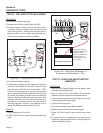
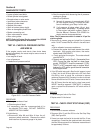
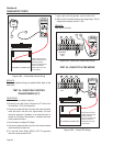
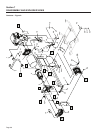
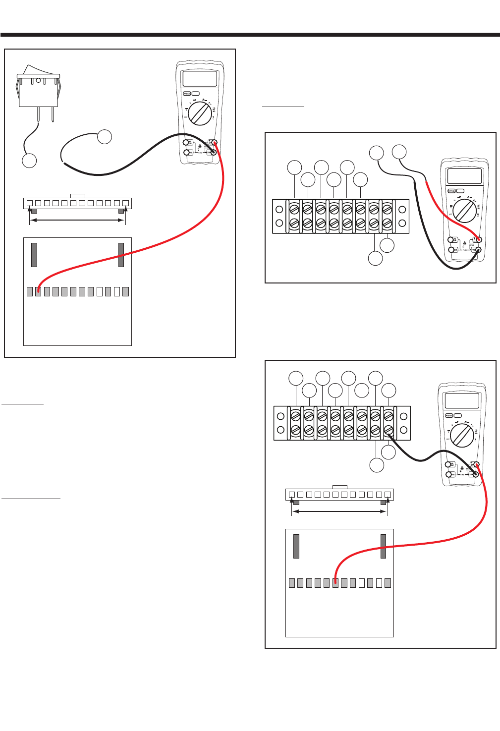
J2 HARNESS CONNECTOR
SW2
00.00
J2-1 J2-12
MAKE SURE THE TEST
PROBE CONNECTOR IS
MAKING CONTACT
WITH THE CONNECTOR.
DOUBLE CHECK TO
MAKE SURE THAT THE
TIP IS SHARP.
0
83
Figure 6-60. – Check Idle Control Wiring
RESULTS:
Repair or replace wiring as needed. Refer back to the
flow chart.
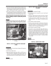
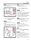
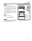
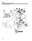
TEST 54 - CHECK IDLE CONTROL
TRANSFORMERS (ICT)
PROCEDURE:
1. Set a voltmeter to measure resistance.
2. Remove the two Idle Control Transformer (ICT) Wires from
Terminal Block 1 (TB1). See Figure 6-61.
3. Connect one meter test lead to one wire and connect the other
meter test lead to the other wire. Approximately 100 ohms
should be measured. If resistance is not measured repair or
replace the Idle Control Transformers. If resistance was mea
-
sured proceed with Step 4.
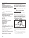
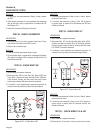
4. Set a voltmeter to measure AC Voltage.
5. Connect one meter test lead to one wire and connect the other
meter test lead to the other wire.
6. Turn the Idle Control Switch (SW2) to OFF. The generator
should be running at about 60 HZ.
7. Apply a light load to the generator, such as a electric drill.
8. When the drill is activated measure the voltage output. The AC
voltage should measure around 1-2 VAC.
RESULTS:
Refer back to flow chart.
TERMINAL
BLOCK
(TB1)
100 ohm
86 15B
167
BLK
0 229
83
BLK
TR2
TR1
Figure 6-61. Check Idle Transformer Wiring
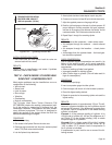
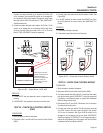
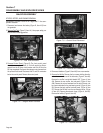
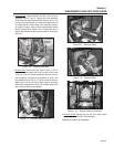
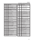
TEST 55 - CHECK TR1 & TR2 WIRING
TB1
J2 HARNESS CONNECTOR
00.00
86 15B
167
BLK
0 229
83
BLK
TR2
TR1
J2-1 J2-12
MAKE SURE THE TEST
PROBE CONNECTOR IS
MAKING CONTACT
WITH THE CONNECTOR.
DOUBLE CHECK TO
MAKE SURE THAT THE
TIP IS SHARP.
Figure 6-62. – Check TR2 Wiring
Section 6
DIAGNOSTIC TESTS
Page 64