


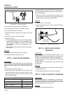
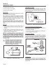
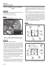
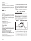

TEST 31 - REMOVE WIRE 18 / SHUTDOWN
LEAD
PROCEDURE:
1. Disconnect Wire 18 from the Stud located above the oil cooler
that extends out From the shrouding.
2. Perform Test 29 again checking for Spark.
RESULTS:
Refer back to Flow Chart.
WIRE 18
SHUTDOWN
LEAD
Figure 6-40. – Wire 18
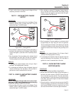
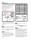
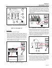
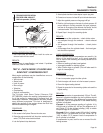
TEST 32 - TEST START STOP RELAY (SSR)
PROCEDURE:
1. Set a voltmeter to measure DC voltage.
2. Remove Wire 15 from Terminal 13 on the Start Stop Relay
(SSR). Connect the positive meter test lead to Wire 15 previ
-
ously removed. Connect the negative meter test lead to frame
ground. 12 VDC should be measured, if it is proceed to Step 3.
If 12 VDC is not measured repair or replace Wire 15 between
the SSR and the Battery Charge Rectifier 2 (BCR2).
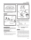
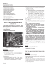
3. With Wire 15 reconnected to the SSR remove Wire 229 from
the SSR. Connect a jumper lead from the terminal of the SSR
that Wire 229 was just removed from and to frame ground. See
Figure 6-43. The relay should energize closed, visually inspect
it to see if it closes. If the relay energizes closed proceed to
Step 4. If the relay does not energize closed replace it.
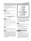
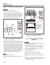
4. Remove Wire 0, Wire 18, Wire 15, Wire 15B, Wire 15, and Wire
14. See Figure 6-42.
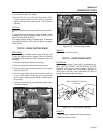
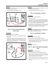
5. Set a voltmeter to measure resistance. Remove jumper lead
from Step 3. Connect meter test leads across TEST POINTS
A continuity/closed should be measured. Connect meter test
leads across TEST POINTS B INFINITY should be measured.
Connect meter test leads across TEST POINTS C. INFINITY
should be measured (See Figure 6-42). If the SSR fails any test
replace it.
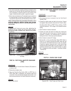
6. Remove Wire 229 from the SSR. Connect a jumper lead
from the terminal of the SSR that Wire 229 was just removed
from and to frame ground. The relay should energize closed.
Set a voltmeter to measure resistance. Connect meter test
leads across TEST POINTS A INFINITY should be measured.
Connect meter test leads across TEST POINTS B continuity/
closed should be measured. Connect meter test leads across
TEST POINTS C continuity/closed should be measured. See
Figure 6.43. If the SSR fails any test replace it.
RESULTS:
Refer to Flow Chart.
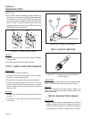
SSR
15B
1413
9 10 12
5
1 2
6
4
8
229
0
18
14
15
15
15
Figure 6-41. – Start Stop Relay (SSR)
SSR
15B
1413
9 10 12
5
1 2
6
4
8
229
0
18
14
TEST POINTS A
TEST POINTS B
TEST POINTS C
15
15
15
Figure 6-42. – Start Stop Relay (SSR) Not Energized
Section 6
DIAGNOSTIC TESTS
Page 54