


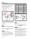

TEST 34 - TEST START STOP RELAY WIRING
PROCEDURE:
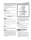
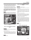
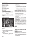
1. Set voltmeter to the diode test range.
2. Disconnect Wire 229 from the Start Stop Relay (SSR).
3. Connect the positive meter test lead to Wire 229 previous
-
ly removed. Connect the negative meter test lead to frame
ground. See Figure 6-47. Place the Start-Run-Stop Switch to
the start position. The meter should read approximately 1.0
VDC. If the correct voltage is indicated, stop testing.
1.0 vdc
SSR
15B
1413
9 10 12
5
1 2
6
4
8
229
0
18
14
15
15
15
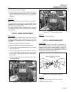
Figure 6-47. – Testing Wire 229 to Ground
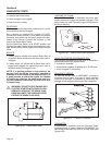
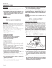
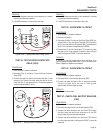
4. Set voltmeter to measure resistance.
5. If voltage was not measured in Step 3 connect one meter test
lead to Wire 229 removed from the SSR. Connect the other
meter test lead to Wire 229 at the Terminal Block 1 (TB1).
Continuity should be measured. If continuity is not measured
repair or replace Wire 229 between SSR and TB1. Remove the
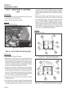
J2 connector the printed circuit board. Connect one meter test
lead to pin location J2-8 (Wire 229) connect the other meter
test lead to Wire 229 at TB1. See Figure 6-48. Be careful not
to damage the pin connectors with the test leads. Continuity
should be measured. If continuity is not measured repair or
replace Wire 229 between the J2 connector and TB1.
RESULTS:
1. If Step 3 passed refer to Flow Chart.
2. If Step 3 failed and Step 5 passed replace the printed circuit
board.
TB1
J2 HARNESS CONNECTOR
00.00
86 15B
167
BLK
0 229
83
BLK
TR2
TR1
J2-1 J2-12
MAKE SURE THE TEST
PROBE CONNECTOR IS
MAKING CONTACT
WITH THE CONNECTOR.
DOUBLE CHECK TO
MAKE SURE THAT THE
TIP IS SHARP.
Figure 6-48. – Testing Wire 229 Between J2
Connector and Terminal Block 1 (TB1)
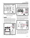
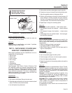
TEST 35 - CHECK AND ADJUST IGNITION
MAGNETOS
PROCEDURE:
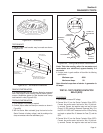
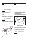
1. See Figure 6-49. Rotate the flywheel until the magnet is under
the module (armature) laminations.
2. Place a 0.008-0.012 inch (0.20-0.30mm) thickness gauge
between the flywheel magnet and the module laminations.
3. Loosen the mounting screws and let the magnet pull the mag
-
neto down against the thickness gauge.
4. Tighten both mounting screws.
5. To remove the thickness gauge, rotate the flywheel.
6. Repeat the above procedure for the second magneto.
7. Repeat Test 29 and check for spark across the spark tester
gap.
8. If air gap was not out of adjustment, remove engine ground
harness from magnetos. Repeat Test 29. If sparking now occurs
replace engine ground harness.
Section 6
DIAGNOSTIC TESTS
Page 56