


RESULTS:
1. If continuity or zero was measured in Step 3 or Step 4 replace
the FSS.
2. (Units without Hourmeter) If correct resistance was measured
refer to flow chart, repair or replace Wire 14 between the FSS
and Resistor (R1).
3. (Units with Hourmeter) Refer back to flow chart.
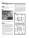
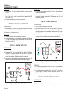
TEST 48 - CHECK HOURMETER
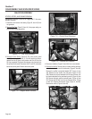
PROCEDURE:
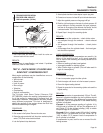
1. Disconnect Wire 14 from the hourmeter. Install new 10 Amp
fuse. Set Start Run Stop Switch (SW1) to start.
2. Check to see if fuse blew open.
RESULTS:
1. If fuse did not blow open replace the hour meter.
2. If fuse still blew repair or replace Wire 14 between the Resistor
(R1) and the Hour Meter (HM) or between the HM and the Fuel
Shutoff Solenoid (FSS).
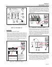
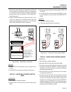
TEST 49 - CHECK WIRE 15B
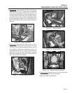
PROCEDURE:
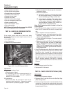
1. Set a voltmeter to measure resistance.
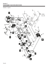
2. Disconnect Wire 15B from the Start Stop Relay (SSR) (see
Figure 6-56) . Connect one meter test lead to Wire 15B previ
-
ously removed. Connect the other meter test lead to frame
ground. Approximately 20K ohms should be measured.
3. If continuity or zero resistance was measured remove the J2
connector from the printed circuit board and repeat Step 2.
20 kohm
SSR
15B
1413
9 10 12
5
1 2
6
4
8
229
0
18
14
15
15
15
Figure 6-56. – Check Wire 15B
RESULTS:
1. If continuity was measured in Step 2 but not in Step 3, replace
the printed circuit board.
2. If continuity was measured in Step 3, Wire 15B is shorted
to ground, repair or replace Wire 15B between the SSR and
printed circuit board.
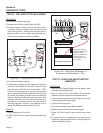
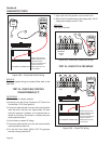
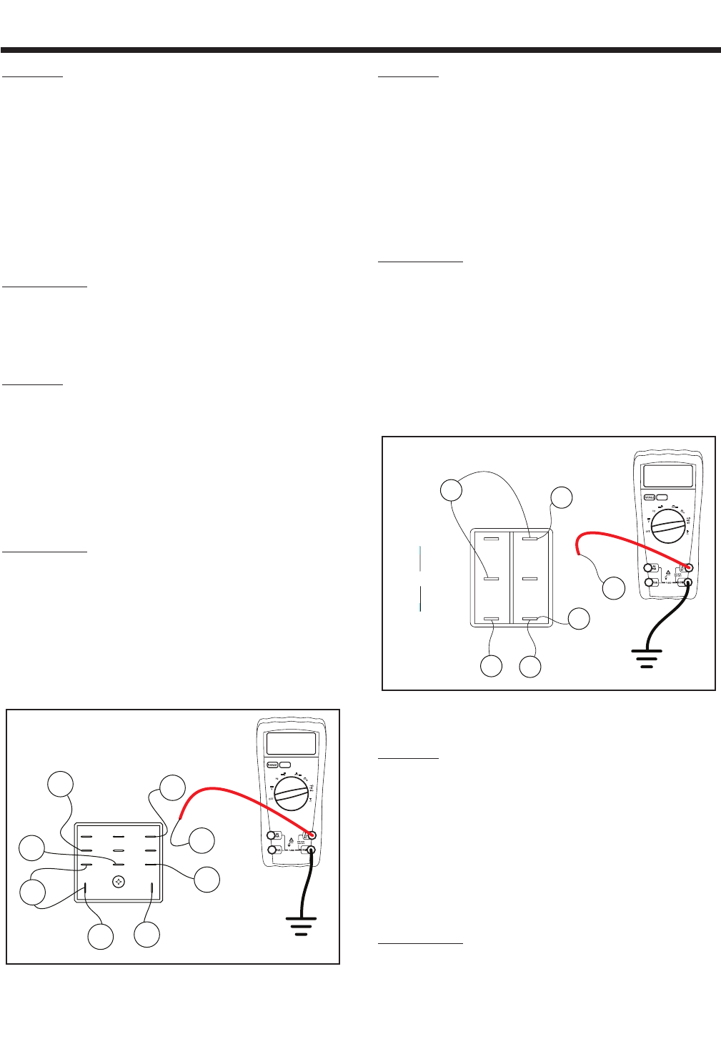
TEST 50 - CHECK WIRE 167
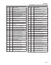
PROCEDURE:
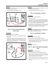
1. Set a voltmeter to measure resistance.
2. Disconnect Wire 167 from the Start-Run-Stop Switch (SW1).
Connect one meter test lead to Wire 167 previously removed.
Connect the other meter test lead to frame ground. See Figure
6-57. INFINITY should be measured.
3. If continuity or zero resistance was measured remove the J2
connector from the printed circuit board and repeat Step 2.
167
(START)
0
15
15
17
4
5
6
1
2
3
RUN
STOP
0
OL
Figure 6-57. Check Wire 167
RESULTS:
1. If continuity was measured in Step 2 but not in Step 3, replace
the printed circuit board.
2. If continuity was measured in Step 3 wire 167 is shorted to
ground, repair or replace Wire 167 between the SW1 and
printed circuit board.
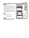
TEST 51 - CHECK WIRES 11S & 44S
PROCEDURE:
1. Set a voltmeter to measure resistance.
2. Disconnect the J2 connector from the printed circuit board.
Section 6
DIAGNOSTIC TESTS
Page 62