


Section 6
DIAGNOSTIC TESTS
Page 43
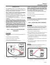
D2
4
14
WIRE 14
REMOVED
14
4
R1
25 ohm
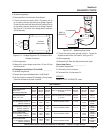
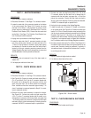
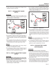
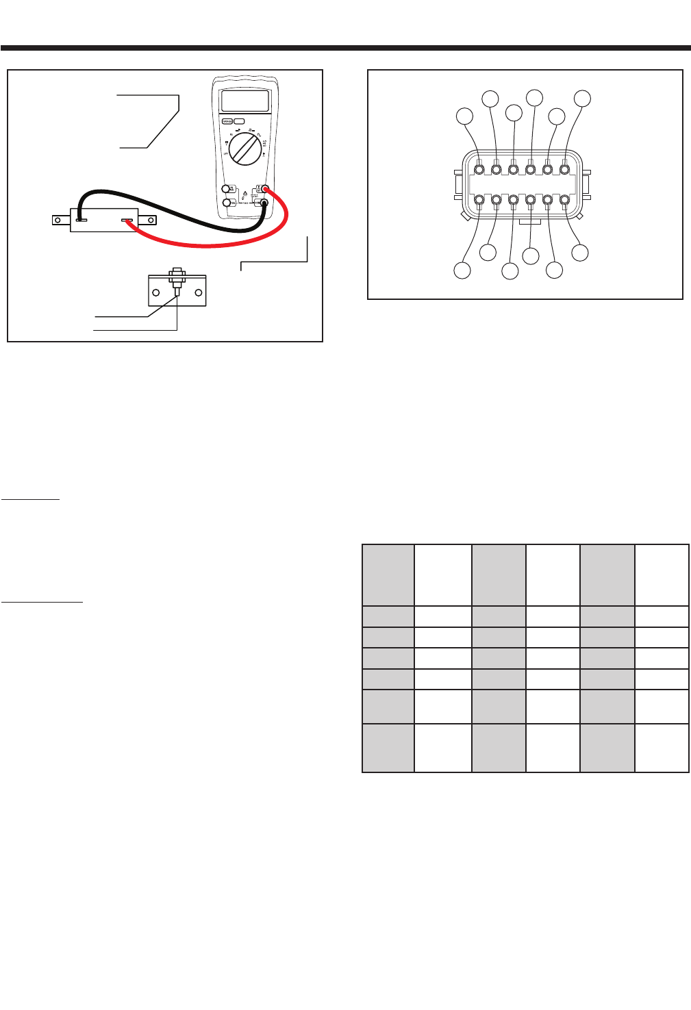
Figure 6-17. – Diode Test Step 9
10. Connect one meter test lead to the top terminal of the resistor
(R1). Connect the other meter test lead to the ground terminal.
INFINITY or an open condition should be measured.
11. Reconnect the six pin connector, reconnect the C1 connector,
reconnect the two wires removed from the resistor (R1).
RESULTS:
1. If the diode or resistor failed any step it should be replaced.
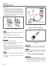
TEST 9 - TEST STATOR
PROCEDURE:
1. From the 50 Amp circuit breaker, disconnect Wires 11 and 44.
2. From the 50 Amp receptacle disconnect Wire 22.
3. Disconnect Connector C1. See Page 17 for connector location.
4. Set a voltmeter to measure resistance.
5. Connect the meter test leads across Stator leads 11 and 22.
Normal power winding resistance should be read.
6. Connect the meter test leads across Stator leads 44 and 22.
Normal power winding resistance should be read.
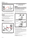
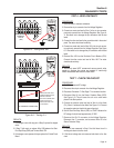
7. Connect the meter test leads across Stator leads 11S (Pin 1)
and Stator lead 44S (Pin 2) at the C1 connector female side.
See Figure 6-18. Be careful not to damage the pin connectors
with the test leads, use paper clips - do not force probes into
connectors. Normal power winding resistance should be read.
8. Connect the meter test leads across Stator leads 66A (Pin 4)
and Stator lead 77A (Pin 5) at the C1 connector female side.
See Figure 6-18. Be careful not to damage the pin connectors
with the test leads, use paper clips - do not force probes into
connectors. Normal battery charge winding resistance should
be read.
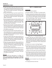
PIN
LOCATION
6
PIN
LOCATION
7
PIN
LOCATION
1
PIN
LOCATION
12
2
77A
66A
55A
44S
11S
0
4
77
66
55
6
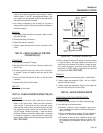
Figure 6-18. – C1 Connector, Female Side
9. Connect the meter test leads across Stator leads 2 (Pin 6)
and Stator lead 6 (Pin 7) at the C1 connector female side. See
Figure 6-18. Be careful not to damage the pin connectors with
the test leads, use paper clips - do not force probes into con-
nectors. Normal excitation winding resistance should be read.
10. Connect the meter test leads across Stator leads 66 (Pin 9)
and Stator lead 77 (Pin 10) at the C1 connector female side.
See Figure 6-18. Be careful not to damage the pin connectors
with the test leads, use paper clips - do not force probes into
connectors. Normal 10 Amp battery charge winding resistance
should be read.
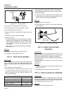
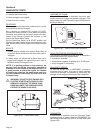
Winding Wire
Numbers
Models
004451-0
004986-0
Models
004582-0,1
004987-0
005209-0
Models
004582-2
004987-1
Models
004583-0
005308-0
Power 11 & 22
0.125 0.088 0.088 0.067
Power 44 & 22 0.125 0.088 0.089 0.067
Sensing 11S & 44S 0.25 0.176 0.176 0.134
Excitation 2 & 6 0.576 0.546 1.270 1.010
Battery
Charge
66A & 77A 0.132 0.111 0.111 0.103
10A
Battery
Charge
66 & 77 0.145 0.125 0.125 0.117
* Resistance values In ohms at 20° C. (68° F.). Actual
readings may vary depending on ambient tempera-
ture. A tolerance of plus or minus 5% is allowed.
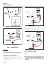
11. Connect the meter test leads across Stator lead 11 and frame
ground. INFINITY should be read.
10. Connect the meter test leads across Stator lead 66A (Pin 4)
and Stator lead 2 (Pin 6) at the C1 connector female side and
frame ground. Be careful not to damage the pin connectors
with the test leads, use paper clips - do not force probes into
connectors. See Figure 6-18. INFINITY should be read.