


Section 6
DIAGNOSTIC TESTS
Page 55
SSR
15B
1413
9 10 12
5
1 2
6
4
8
229
0
18
14
TEST POINTS A
TEST POINTS B
JUMPER LEAD
ADDED TO GROUND
TEST POINTS C
15
15
15
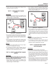
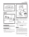
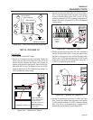
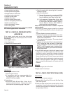
Figure 6-43. – Start Stop Relay (SSR) Energized
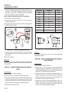
TEST 33 - TEST WIRE 167
PROCEDURE:
1. Set a voltmeter to measure DC voltage.
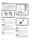
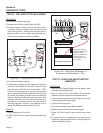
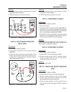
2. Remove the J2 connector from the circuit board. Connect the
positive meter test lead to Pin Location J2-5, Wire 167 on the
removed harness connector. See Figure 6-44 Connect the
negative meter test lead to frame ground. Place the Start-Run-
Stop switch (SW1) to start. The engine will crank and 12 VDC
should be measured. If 12 VDC is measured, stop testing. If 12
VDC is not measured continue testing.
J2 HARNESS CONNECTOR
12 vdc
J2-1 J2-12
MAKE SURE THE TEST
PROBE CONNECTOR IS
MAKING CONTACT
WITH THE CONNECTOR.
DOUBLE CHECK TO
MAKE SURE THAT THE
TIP IS SHARP.
Figure 6-44. – Test Wire 167, Step 2
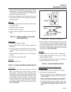
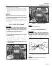
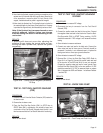
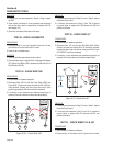
3. Connect the positive test lead to Wire 167 at Terminal Block 1
(TB1). Connect the negative meter test lead to frame ground.
Place the Start-Run-Stop Switch (SW1) to start. 12 VDC
should be measured. If 12 VDC is measured, replace Wire 167
between TB1 and the J2 connector. If 12 VDC is not measured
continue testing.
TERMINAL
BLOCK
(TB1)
12 vdc
86 15B
167
BLK
0 229
83
BLK
TR2
TR1
Figure 6-45. – Test Wire 167, Step 3
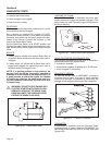
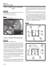
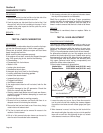
4. Connect the positive test lead to Wire 167 with it connected at
the Start Run Stop Switch (SW1). Connect the negative meter
test lead to frame ground. Place the Start-Run-Stop Switch
(SW1) to start. 12 VDC should be measured. If 12 VDC is mea-
sured, repair or replace Wire 167 between SW1 and the TB1. If
12 VDC is not measured continue testing.
12 vdc
167
STOP
0
15
15
17
4
5
6
1
2
3
RUN
START
STEP 4
STEP 5
0
Figure 6-46. – Test Wire 167, Steps 4 & 5
5. Connect the positive meter test to Wire 15 at SW1. See Figure
6-46. Connect the negative meter test lead to frame ground.
12 VDC should be measured. If 12 VDC is measured, replace
SW1. If 12 VDC is not measured repair or replace wire 15
between SW1 and the Starter Contactor Relay (SCR).