


Section 6
DIAGNOSTIC TESTS
Page 51
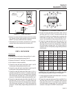
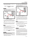
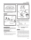
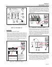
Figure 6-32. – Tachometer
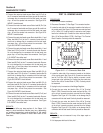
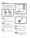
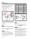
TEST BRACKET:
A starter motor test bracket may be made as shown
in Figure 6-33.
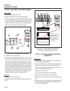
METAL STOCK
1/4" THICK STEEL
12"
1.0"
4"
2"
2.625"
3.5"
0.5"
0.5"
DRILL TWO HOLES — 1/2"
FOR STARTER
MOUNTING BRACKET
DRILL TWO HOLES — 1/2"
FOR MOUNTING TACHOMETER
TAP FOR 1/4-20 NC SCREWS
Figure 6-33. – Test Bracket Dimensions
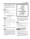
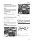
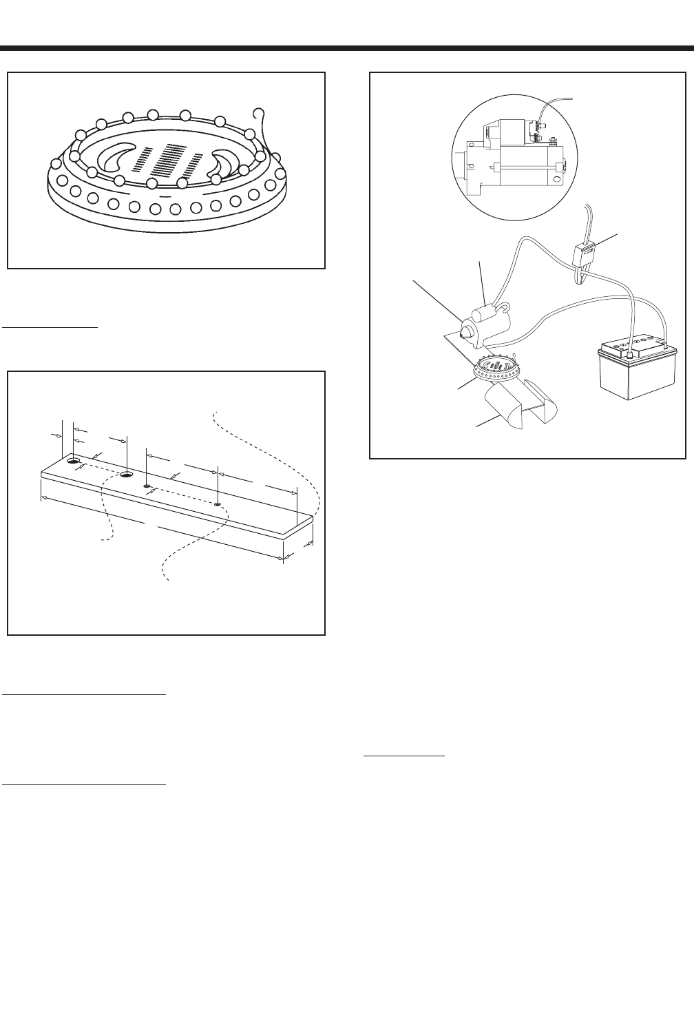
REMOVE STARTER MOTOR:
It is recommended that the Starter Motor be removed
from the engine when testing Starter Motor perfor-
mance. Assemble starter to test bracket and clamp
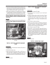
test bracket in vise (Figure 6-34).
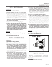
TESTING STARTER MOTOR:
1. A fully charged 12 volt battery is required.
2. Connect jumper cables and clamp-on ammeter as shown in
Figure 6-34.
3. With the Starter Motor activated (jump the terminal on the
Starter Contactor to battery voltage), note the reading on the
clamp-on ammeter and on the tachometer (rpm).
STARTER
CONTACTOR
STARTER
MOTOR
TACHOMETER
12 VOLT
BATTERY
CLAMP ON
AMP METER
VISE
Figure 6-34 – Testing Starter Motor Performance
Note: Take the reading after the ammeter and
tachometer are stabilized, approximately 2-4
seconds.
4. A starter motor in good condition will be within the following
specifications:
Minimum rpm 4500
Maximum Amps 50
Note: Nominal amp draw of starter in generator is
60 amps.
TEST 26 - TEST STARTER CONTACTOR
RELAY (SCR)
PROCEDURE:
1. Set voltmeter to measure DC voltage.
2. Remove Wire 15 from the Starter Contactor Relay (SCR).
Connect the positive meter test lead to Wire 15 previous
-
ly removed. Connect the negative meter test lead to frame
Ground. 12 VDC should be measured. Reconnect Wire 15 to
the SCR. If 12 VDC is NOT measured on Wire 15 Stop Testing
and repair or replace Wire 15 between the Fuse (F1) and the
SCR.
3. Remove Wire 13 from the Starter Contactor Relay (SCR).
Connect the positive meter test lead to Wire 13 previous
-
ly removed. Connect the negative meter test lead to frame