


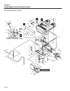

MAJOR DISASSEMBLY
STATOR, ROTOR, AND ENGINE REMOVAL.
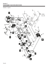
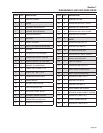
Reference Figures A and B on Pages 68-71 for com-
ponent location.
1. Disconnect and remove the battery (Figure B, Item #15) from
the generator.
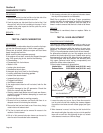
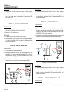
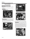
2. Remove Fuel Tank (Figure B, Item #4). Use proper safety pre-
cautions when handling gasoline.
Figure 7-1. – Fuel Tank Removed
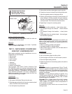
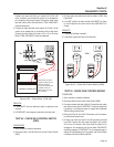
3. Remove Control Panel. (Figure B) The front control panel
should be removed and Wires 11 & 44 will need to be discon-
nected from the 50 Amp circuit breaker and Wire 22 from the
50 Amp receptacle. Disconnect the stepper motor harness from
the printed circuit board. Disconnect the C1 and C2 connectors
below the control panel. Remove the control panel.
Figure 7-2. – Stepper Motor Harness
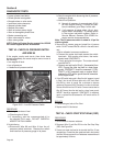
Figure 7-3. – Control Panel Removed
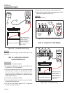
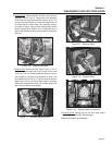
Figure 7-4. – Remove Air Deflector
4. Remove air deflector (Figure B, Item #45) from cross member.
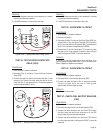
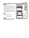
5. Remove the Muffler. Remove the four screws holding the alter-
nator air cover on the rear of the alternator, (Figure A, Item #8).
Remove the muffler heat shield labeled HOT, Figure A, Item
#34. Remove the rear muffler box end panel, (Figure A, Item
#38). Remove the nut and washers from the top of the rear rub-
ber mounts attached to the rear bearing carrier, (Figure A, Item
32). Remove the back muffler box back panel, (Figure A, Item
37). Remove the M8 bolt from the rear bearing carrier, (Figure
A, Item #15). Remove the exhaust clamp, (Figure A, Item 35).
Remove the muffler, (Figure A, Item #6).
Figure 7-5. – Remove Muffler
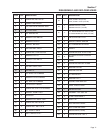
Section 7
DISASSEMBLY AND EXPLODED VIEWS
Page 66