16
2000 Owner’s Manual
1) Remove the screws holding the equipment access panel to the front
of the spa cabinet and set the panel aside.
2) Loosen the four screws located on the front of the black equipment
control can and remove the door from the control can to allow
access to the four wire connection terminal block.
3) Attach 1” rigid non-metallic conduit to the conduit nipple located in
the pedestal base on the side of the spa and run required conductors
through the conduit to the equipment can.
4) Connect the four wires to the equipment system terminal block
(TB1) as indicated on the wiring diagram in the back of this manual.
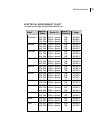
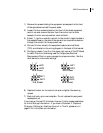
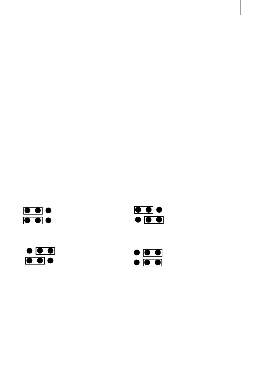
5) Configure jumpers 1 and 2 on the upper right corner of the PC Board
to match the circuit size being used for the spa (see Electrical
Requirements Chart on previous page for proper wire size). See the
chart below for the correct settings.
6) Replace the door on the control can and re-tighten the securing
screws.
7) Electrical hook-up is now complete. Do not replace the equipment
access panel yet.
If you have an Aurora HP, Interlude, Arena or Triad or please read below
for Initial Start-up Information. If you have a Chairman II, Diplomat,
C h a i rman, Californian, Nautilus, Aurora II or Triad II, please turn to
page 27 for Initial Start-up inform a t i o n .
30 A Circuit
40 A Circuit
1 2
JMP1
JMP2
1 2
JMP1
JMP2
1 2
JMP1
JMP2
1 2
JMP1
JMP2
15 A Circuit
50 A Circuit


