C2674M-C (7/09) 29
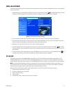
VIDEO ADJUSTMENT
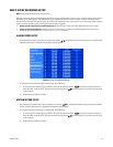
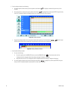
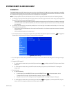
The video adjustment option allows you to set the characteristics (brightness, contrast, and color) of displayed video, and how it is recorded and
stored for each camera.
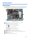
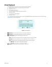
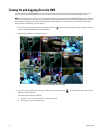
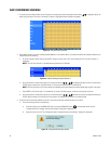
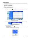
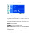
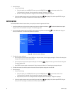
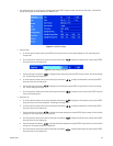
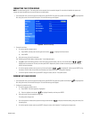
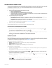
1. From the options pane, on the front panel or remote control, press the up/down arrow buttons to highlight Video Adjustment. Using
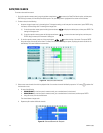
the mouse, click Video Adjustment. The Video Adjustment option is highlighted and the property settings are displayed.
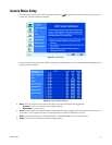
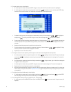
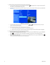
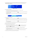
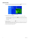
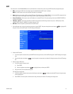
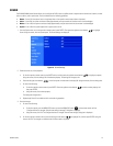
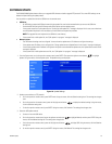
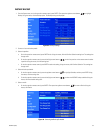
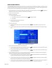
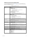
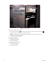
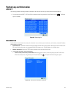
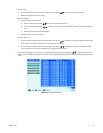
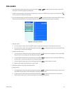
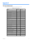
Figure 15. Video Adjustment Option Settings
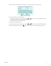
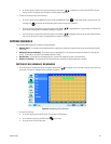
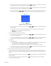
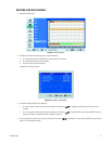
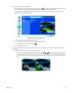
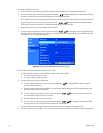
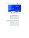
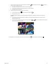
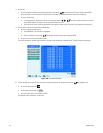
2. On the front panel or remote control, press ENTER. Using the mouse, click Channel. The Channel 01 name box is highlighted.
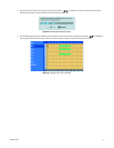
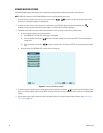
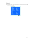
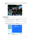
3. Use the front panel, remote control, or mouse to select a channel. Adjust the brightness, contrast, and color of the display on the monitor.
Be sure to preview the video display in the preview window before finalizing your selection.
4. Repeat step 3 for each camera for which you want to adjust the video output display.
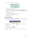
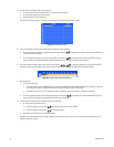
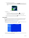
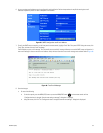
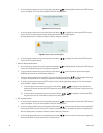
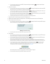
5. To reset the settings for the current channel using the front panel or remote control, press the up/down arrow buttons to highlight
“Restore to Default”, and then press ENTER. Using the mouse, click Restore to Default. The setting for the current channels are reset to the
factory defaults.
6. To accept the settings and exit Video Adjustment, press the MENU/ESC button on the front panel or press the MENU/ESC button on
the remote control. Using the mouse, click Video Adjustment. The Video Adjustment option is highlighted.
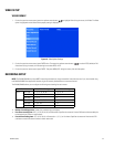
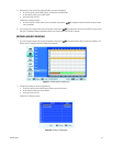
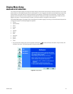
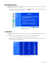
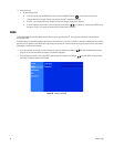
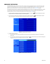
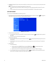
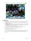
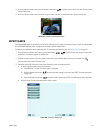
PTZ SETUP
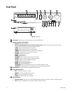
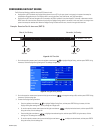
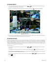
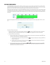
PTZ devices are connected to the DX4500/DX4600 using the DATA 1 and DATA 2 RS-422/RS-485 ports located on the back of the unit. The
DX4508/DX4608 supports up to 8 serial PTZ cameras; the DX4516/DX4616 supports up to 16 serial PTZ cameras. Multiple PTZ cameras are
connected by daisy-chaining the camera connections. The DX4500/DX4600 allows you to address and control multiple PTZ cameras individually.
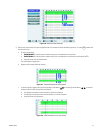
NOTE: You might experience operational issues when a camera device is not correctly terminated. When connecting camera devices, use a
normal load termination of 75 ohms. When looping through DVR inputs, ensure that the signal is terminated at the end device. For additional
information about terminating a specific camera device, refer to the device’s installation manual.
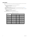
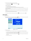
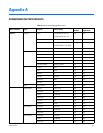
Before you perform the PTZ setup procedure, you will need the following information for each PTZ camera being configured:
• Channel to which the PTZ camera is attached
• Data port to which the camera is connected
• Pelco D and Pelco P address
• Camera protocol
• Communication settings: Baud rate, parity, data bits, and stop bits