5-22
(3) Measure the distortion on the audio analyzer checking that the result is within the
specification shown in Table 5-44.
(4) Measure the absolute level on the audio analyzer (in dBm) and record this level as a
reference.
(5) Set the UUT mod source to each of the frequencies shown in Table 5-44. Subtract the level
measured on the audio analyzer at each frequency from that recorded in (4) checking that the
results are within specification.
External frequency standard input
Specification
External input Front-panel BNC connector accepts an input of 1 MHz or 10 MHz at 220 mV RMS to
1.8 V RMS into 1 kΩ.
Test equipment
Description Minimum specification Example
Signal generator 220 mV to 1.8 V RMS, 1 MHz to 10 MHz IFR 2041 or 2030
Test procedure
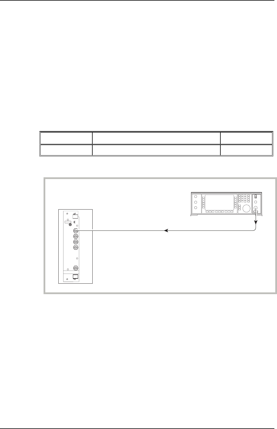
UUT
C2570
FREQ STD
I/O
RF OUTPUT
Signal generator
Fig. 5-15 External standard test set-up.
(1) Connect the test equipment as shown in Fig. 5-15.
(2) On the UUT set:
Freq Std External 1 Direct
(3) Set the signal generator to RF level 220 mV EMF, carrier frequency 1 MHz.
(4) Using Table 5-45, check that no external standard error messages are displayed on the UUT.
(5) Set the signal generator to 1.8 V EMF and repeat (4).
(6) On the UUT set
Freq Std External 10 Indirect
(7) Set the signal generator to carrier frequency 10 MHz and repeat (4).
(8) Set the signal generator to 220 mV and repeat (4).


