


5-20
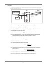
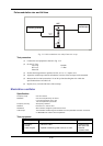
Pulse modulation rise and fall time
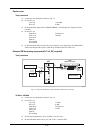
C2567
OUTPUT
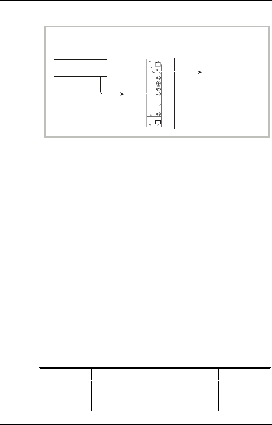
Function generator
RF
OUT
UUT
PULSE
INPUT
Oscilloscope
Fig. 5-12 Pulse modulation rise and fall time test set-up
Test procedure
(1) Connect the test equipment as shown in Fig. 5-12.
(2) On the UUT set:
Carr Freq 50 MHz
RF Level +7 dBm
Pulse ON
(3) Set the function generator to produce 10 kHz, 0 V to +5 V square wave.
(4) Adjust the oscilloscope controls such that the rise time of the envelope can be measured.
(5) Measure the rise time between the 10% to 90% points checking that it is within the
specification shown in Table 5-42.
(6) Repeat (4) to (5) for the fall time of the envelope.
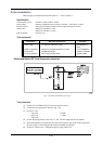
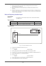
Modulation oscillator
Specification
Frequency range 0.01 Hz to 20 kHz.
Resolution 0.01 Hz for frequencies up to 100 Hz,
0.1 Hz for frequencies up to 1 kHz,
1 Hz for frequencies up to 20 kHz.
Frequency accuracy As frequency standard.
Distortion Less than 0.1% THD at 1 kHz.
Waveforms Sine to 20 kHz, triangle or square wave to 3 kHz.
Audio output The modulation oscillator signal is available on a front-panel BNC connector at a level of
2 V RMS EMF from a 600 Ω source impedance.
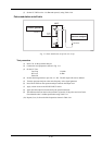
Test equipment
Description Minimum specification Example
Frequency
counter
9 kHz to 2.4 GHz Agilent 53181A
with option 030
Audio analyzer Capable of measuring THD of 0.01% at 1 kHz Rohde &
Schwarz UPA3