5-18
Pulse modulation
Does not apply to instruments fitted with Option 11 — refer to Annex A.
Specification
Carrier frequency range 32 MHz to 2.4 GHz, usable to 10 MHz.
RF level range Maximum guaranteed output is reduced to +20 dBm, +14 dBm above 1.2 GHz.
RF level accuracy When pulse modulation is enabled, adds ±0.5 dB to the RF level accuracy.
ON/OFF ratio Better than 45 dB below 1.2 GHz.
Better than 40 dB above 1.2 GHz.
Rise and fall time
Less than 10 µs.
Test equipment
Description Minimum specification Example
Power meter
±0.1 dB from 9 kHz to 2.4 GHz
IFR 6960B and
6912
Spectrum analyzer Frequency coverage 32 MHz to 2.4 GHz Anritsu MS2602A
Oscilloscope 100 MHz bandwidth Tektronix TDS 220
Function generator DC to 10 kHz square wave Agilent 3325B
Pulse modulation RF level frequency response
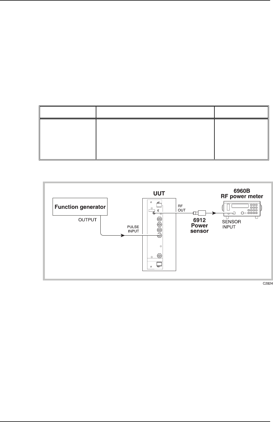
Fig. 5-10 Pulse modulation test set-up
Test procedure
(1) Perform AUTO ZERO and AUTO CAL on the power meter.
(2) Connect the test equipment as shown in Fig. 5-10.
(3) On the UUT set:
Carr Freq 32 MHz
RF Level
−7 dBm
Pulse ON
(4) Set the function generator to provide +5 V DC. The RF output will now be enabled.
(5) Record the output level measured by the power meter against each of the carrier frequencies
shown in Table 5-38 checking that the results are within specification.
(6) Set the UUT RF level to +4 dBm and repeat (5) using Table 5-39.


