


5-14
Phase modulation
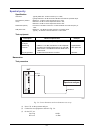
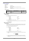
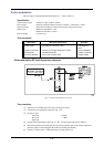
Specification
Deviation 0 to 10 radians.
Resolution 3 digits or 0.01 radians.
Accuracy at 1 kHz ±5% of indicated deviation excluding residual phase modulation.
Bandwidth (3 dB) 100 Hz to 10 kHz.
Distortion Less than 3% at 10 radians at 1 kHz modulation rate. Typically <0.5% for deviations up
to 1 radian at 1 kHz.
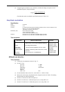
Test equipment
Description Minimum specification Example
Modulation meter
ΦM and FM accuracy ±2% at 1 kHz modulation
frequency
IFR 2305 with
distortion option
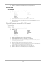
Phase modulation
Test procedure
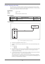
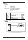
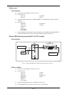
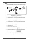
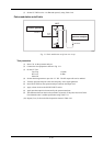
(1) Connect the test equipment as shown in Fig. 5-7.
(2) On the UUT set:
Carr Freq 10.5 MHz
RF Level 0 dBm
Source On
Mod Mode PM Internal
PM1 Level 10 rad
(3) On the modulation meter, select CAL,
ΦM.
(4) Measure the
ΦM accuracy and distortion checking that the results are within the specification
shown in Table 5-28.
Phase modulation flatness
Test procedure
For this test, the phase modulation figures are calculated from readings taken with the modulation
meter set to FM. No allowances need to be made for the modulation source frequency accuracy
since it is derived from the reference oscillator in the UUT.
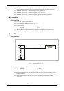
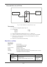
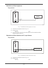
(1) Connect the test equipment as shown in Fig. 5-7.
(2) On the UUT set:
Carr Freq 15 MHz
RF Level 0 dBm
Mod Mode PM Internal
Source On
Mod On
PM1 Level 10 rad
(3) On the modulation meter, select CAL, FM, 50 Hz
Þ 15 kHz LF filter.
(4) Measure the deviation on the modulation meter and calculate the phase modulation using the
formula:
þ
ý
ü
î
í
ì
=Φ
(Hz) freq mod
(Hz) dev FM
M
(5) On the UUT set mod source to each of the frequencies shown in Table 5-29, measure the
deviation on the modulation meter and calculate the phase modulation for each step using the
formula in (4).