


5-4
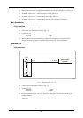
RF level frequency response
Test procedure
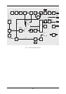
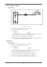
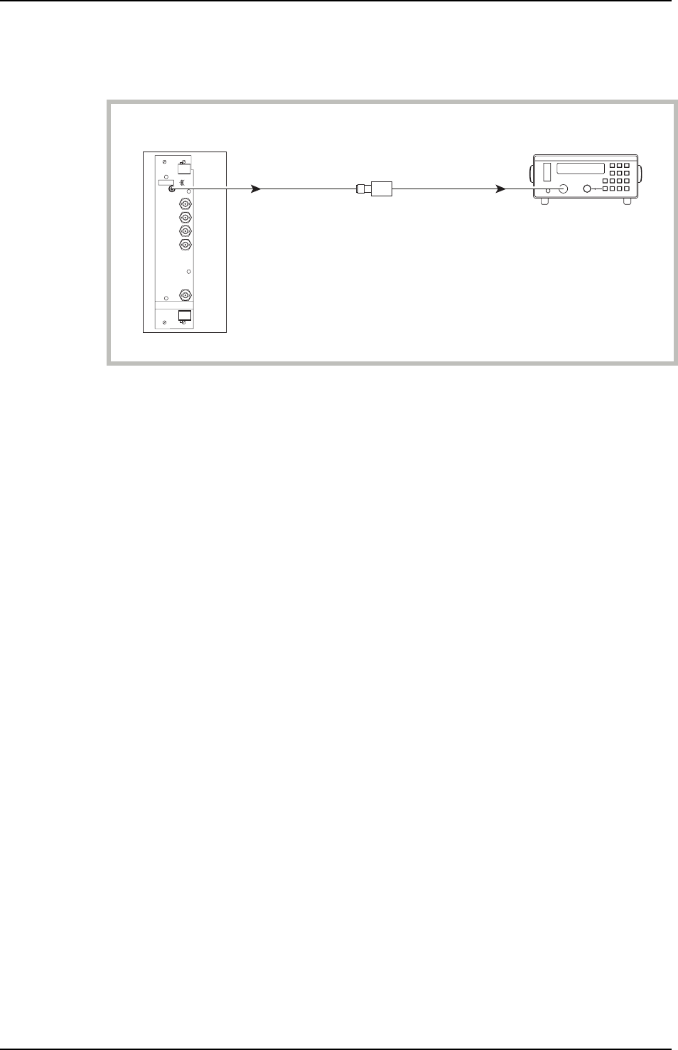
UUT
C2558
RF OUT
SENSOR
INPUT
6960B
RF power meter
6932
Power
sensor
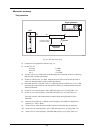
Fig. 5-1 RF output test set-up
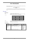
(1) Perform AUTO ZERO and AUTO CAL on the power meter.
(2) Connect the test equipment as shown in Fig. 5-1.
(3) On the UUT set:
Carr Freq 30 kHz
RF Level 0 dBm
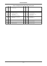
(4) Record the output level measured by the power meter against each of the carrier frequencies
shown in Table 5-1 checking that the results are within specification.
(5) Set the UUT RF level to +7 dBm and repeat (4) using Table 5-2.
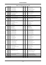
(6) Set the UUT RF level to +25 dBm and repeat (4) using Table 5-3, decreasing the RF level to
+19 dBm when testing at carrier frequencies above 1.2 GHz.
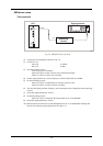
ALC linearity
Test procedure
(1) Perform AUTO ZERO and AUTO CAL on the power meter.
(2) Connect the test equipment as shown in Fig. 5-1.
(3) On the UUT set:
Carr Freq 2.5 MHz
RF Level −4 dBm
(4) Record the output level measured by the power meter against each of the steps shown in
Table 5-4 checking that the results are within specification.
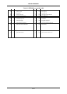
(5) Set the UUT carrier frequency to 950 MHz and repeat (4) using Table 5-5.
(6) Set the UUT carrier frequency to 1200 MHz and repeat (4) using Table 5-6.
(7) Set the UUT carrier frequency to 1900 MHz and repeat (4) using Table 5-7.
(8) Set the UUT carrier frequency to 2400 MHz and repeat (4) using Table 5-8.