


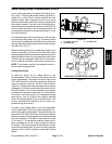
Groundsmaster 4500--D/4700--D Hydraulic SystemPage 4 -- 31
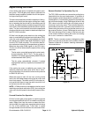
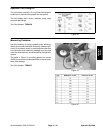
Engine Cooling Fan Circuit
A four section gear pump is coupled to the piston (trac-
tion) pump. The final gear p ump section (farthest from
the piston pump) supplies hydraulic flow for the hydrau-
lic engine cooling fan motor.
The fan controlmanifold controls the operationof the hy-
draulic motor that drives the engine cooling fan in addi-
tion to including the flow divider for the steering and lift
circuits. The electronically controlled proportional relief
valve (PRV) inthe manifold controls theoil flow to thefan
motor. The fan control manifold controls the speed and
direction of the fan motor based on electrical output from
the TEC--5002 controller.
Oil flow from the gear pump section to the cooling fan
motor is controlled by the proportional relief valve (PRV)
in the fan control manifold. This valve adjusts fan circuit
flow based on a PWM (Pulse Wid th Modulation) signal
from the TEC--5002 controller. The controller uses en-
gine coolant and hydraulic oil temperatures as inputs to
determine the proper PWM signal for the PRV valve.
The fan circuit flow determines the speed of the cooling
fan motor.
The fan motor runs at half speed until coolant reach-
es approximately 165
o
F(74
o
C). The fan motor in-
creases to full speed (approximately 2800 RPM) as
coolant reaches 180
o
F(82
o
C).
The fan motor automatically reverses if coolant
reaches 203
o
F(95
o
C) or hydraulic oil reaches 212
o
F
(100
o
C).
If the cooling fan motor is stalled for any r eason, t he
manifold proportional relief valve (PRV) has a secon-
dary function as a circuit relief to limit fan motor pressure
to 3000 PSI (207 b ar).
When the engine is shut off, the over--running inertia
load of the fan blades keeps driving the fan motor and
turns it into a pump. The check valve (CV) in the fan con-
trol manifold will open to keep the motor circuit full of oil
so t he fan motor will not cavitate.
NOTE: If PWM current is not available to the fan control
manifold proportional relief valve (PRV), the cooling fan
motor will run at full speed in t he normal (forward) direc-
tion.
Forward Direction Fan Operation
Oil flow from the gear pump section is sent through the
de--energized solenoid valve S1 to rotate the cooling fan
motor. Return flow from the motor re--enters the man-
ifold (port M2), through the de--energized solenoid valve
S1, out of the manifold (port T) and then is routed
through the deck control manifold, oil cooler and oil filter.
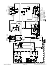
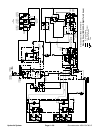
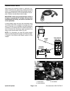
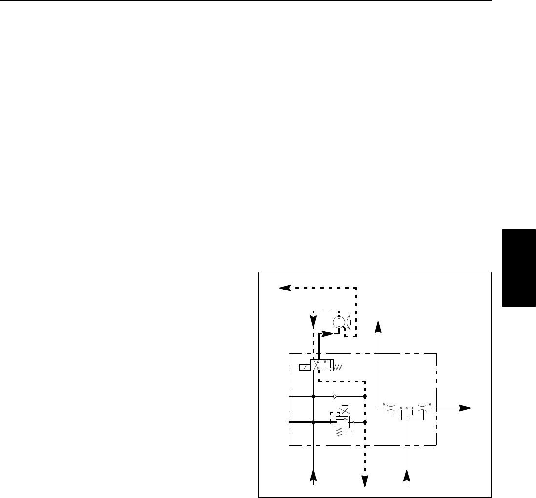
Reverse Di rection Fan Operation (Fig. 24)
The TEC--5002 controller can reverse the cooling fan to
clean debris from the rear intake screen. If hydraulic oil
and/or engine coolant temperatures increase to an un-
suitable level or if a manual fan reversal is requested via
the InfoCenter display, a high PWM signal is sent to the
PRV valve to slow the cooling fan and direct pump oil
flow away from the fan motor. The controller then ener-
gizes solenoid valve S1 in the fan control manifold to re -
verse cooling fan motor oil flow so that the motor runs in
the reverse direction. A lower PWM signal is sent to the
PRV valve allowing oil flow to return to the fan motor but
in the reverse direction causing the motor and cooling
fantoruninreverseforashorttime.
NOTE: The fan reversal process is designed to clean
debris from the rear screen but not the radiator. Refer to
Operator’s Manual for radiator cleaning maintenance
recommendations.
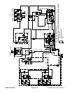
Figure 24
REVERSE
FROM GEAR
TO OIL
TO RESERVOIR
TO LIFT/LOWER
CIRCUIT
TO STEERING
CIRCUIT
PUMP SECTION
FROM GEAR
PUMP SECTION
DIRECTION
T
PRV
S1
CV
FD
P2P1
ST
L
M1 M2
50/50FLOW
DIVIDER
FANCONTROL
MANIFOLD
G2
G1
COOLER
Hydraulic
System