


Groundsmaster 4500--D/4700--DPage 6 -- 30Axles, Planetaries and Brakes
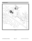
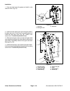
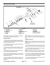
Input Shaft/Pinion Gear
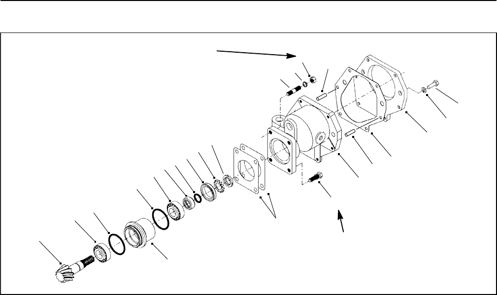
Figure 35
1
1. Nut (2 used)
2. Lock washer (2 used)
3. Stud (2 used)
4. Lock nut
5. Stake washer
6. Oil seal
7. O-ring
8. Seal collar
9. Bearing
10. O-ring
11. Input shaft/pinion gear
12. Bearing case
13. Shim
14. Screw (2 used)
15. Gear case
16. Gasket
17. Cover plate
18. Dowel pin
19. Lock washer (6 used)
20. Cap screw ( 6 used)
2
3
4
5
6
7
8
9
10
9
11
12
13
14
15
16
17
10
18
18
35 to 41 ft--lb
(47 to 56 N--m)
35 to 41 ft--lb
(47to56N--m)
19
20
The following procedures assume the rear axle assem-
bly has been removed from the machine.
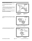
Removal (Fig. 35)
1. Remove the cover plate, gasket and gear case as-
sembly from the axle assembly. Remove the gasket and
any remaining gasket material.
2. Remove the retaining rings and the driven gear from
the input shaft/pinion gear.
3. Remove input shaft/pinion gear assembly from the
gear case. Remove the shims and bearing case O-
rings.
4. Release the stake washer and remove the lock nut.
Remove and discard the stake washer.
5. Drive the input shaft/pinion gear out from the outer
bearing cone and bearing case. Remove and discard
the oil seal and O-ring.
6. Inspect all gears, shafts, bearings, spacers and
cases for damage and wear. Replace components as
necessary.
NOTE: Replacement input shaft/pinion gear (item 11)
is only available in matched set with differential ring
gear.
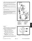
Installation (Fig. 35)
NOTE: When installing bearing cones onto the input
shaft/pinion gear, press only on the inner race of the
bearing cone.
1. If the inner bearing cone was removed, press a new
bearing cone all theway onto the input shaft/pinion gear.
2. Place the shaft and bearing assembly in the bearing
case and install t h e outer b earing cone.
NOTE: The bearings must be completely seated.
There should be no input shaft/pinion gear end play.
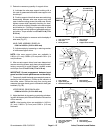
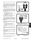
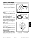
3. Coat a new oil seal with grease and install as shown
(Fig. 36). The seal should be installed with the garter
spring towards the hydraulic motor location.
4. Coat new O-ring with grease. Install O-ring in the oil
seal collar and install the collar.