


Groundsmaster 4500--D/4700--D Hydraulic SystemPage 4 -- 67
Procedure for Lift/Lower Circuit Relief Pressure
Test
The lift/lower circuit relief pressure test should be per-
formed to make sure that the cutting unit lift and lower
circuit relief pressure is correct.
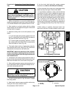
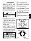
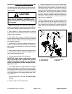
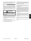
CAUTION
Prevent personal injury and/or damage to equip-
ment. Read all WARNINGS, CAUTIONS and Pre-
cautions for Hydraulic Testing at the beginning
of this section.
1. Make sure hydraulic oil is at normal operating tem-
perature by operatingthe machinefor approximately ten
(10) minutes. Make sure the hydraulic reservoir is full.
2. Park machine on a level surface with the cutting
decks fully raised. Apply the parking brake and stop en-
gine.
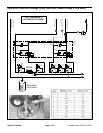
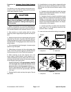
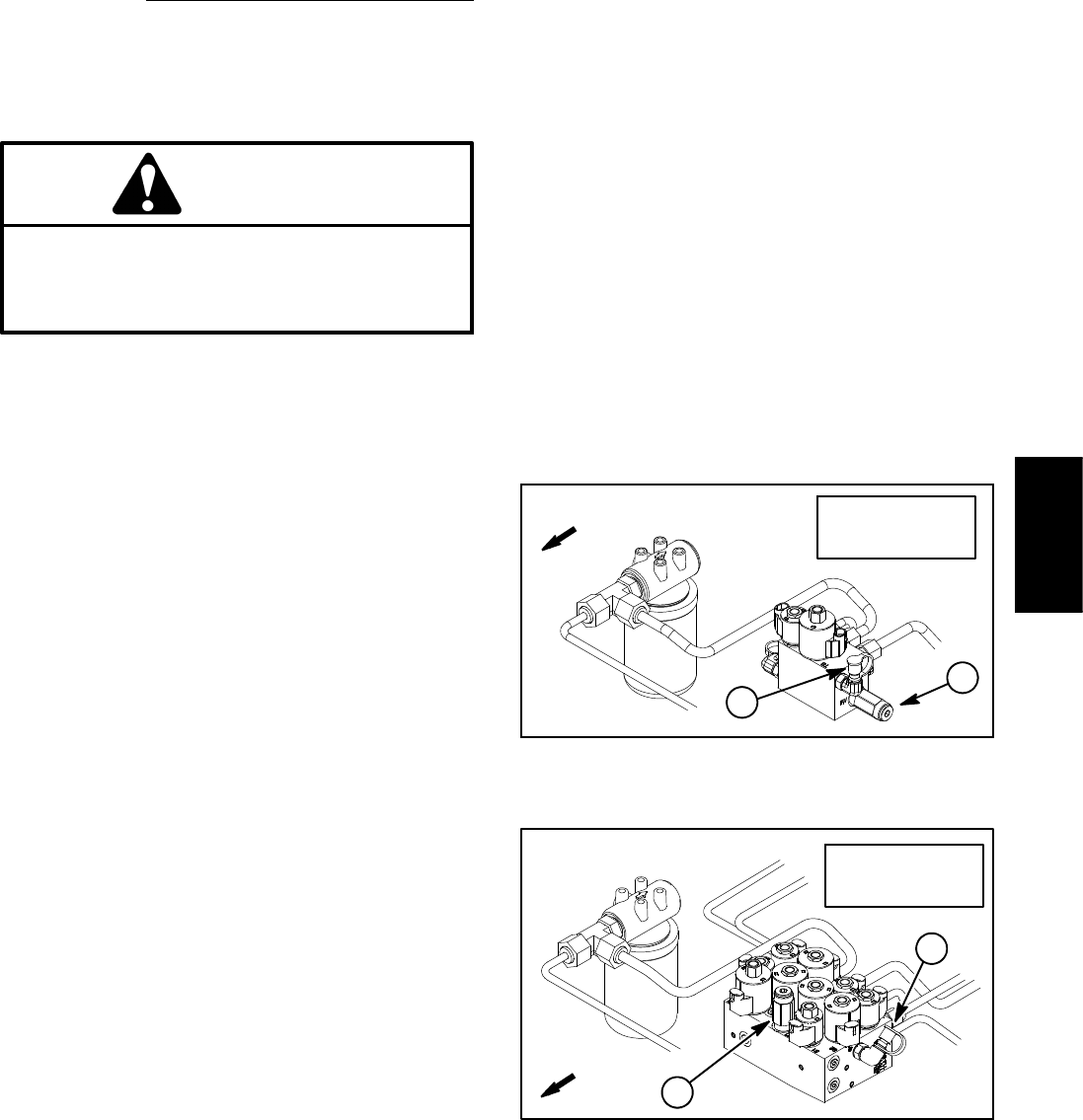
3. Raise and support hood to gain access to lift control
manifold (Fig. 54 or 55). Connect a 5000 PSI (350 bar)
pressure gauge with hydraulic hose attached to lift man-
ifold test port G1. Route gauge hose to allow hood to be
safely lowered.
4. Sit on the seat and start the engine. Increase engine
speed to high idle speed.
5. While sitting on the seat, with the cutting decks fully
raised, monitor the pressure gauge to identify lift/lower
circuit pressure with no load. Record this pressure.
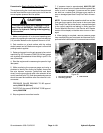
6. While remaining on the seat, depress rear of lift
switch (raise) to allow lift/lower circuit pressure to in-
crease. Momentarily hold the switch with the lift cylin-
ders fully retracted while looking at the pressure gauge
as the lift/lower relief valve opens.
GAUGE READING TO BE approximately 1600 PSI
(110 bar) higher than measured lift/lower circuit
pressure with no load from step 5 above (e.g. if
circuit no load pressure is 300 PSI (21 bar), lift/lower
relief pressure should be approximately 1900 PSI
(131 bar))
7. Release the lift switch and stop the engine. Record
test results.
8. If specification is not met, adjust or clean relief valve
locatedintheliftcontrolmanifold(seeLiftControlMan-
ifold Service in the Service and Repairs section of this
chapter).
A. If pressure is too high, adjust the relief valve (see
Adjust Control Manifold Relief Valves in the Adjust-
ments section of this chapter).
B. If pressure is too low, check for restriction in gear
pump intake line. Check the lift cylinders for internal
leakage. If pump intake line is not restricted and lift
cylinders are not leaking, adjust the relief valve (see
Adjust Control Manifold Relief Valves in the Adjust-
ments section of this chapter).
C. If pressure is still too low after relief valve adjust-
ment, pump P4 or lift cylinder(s) should be sus-
pected of wear or damage.
9. Lower and secure hood after testing is completed.
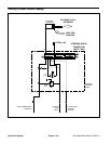
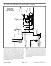
1. Test port G1 2. Relief valve
Figure 54
GM 4500--D
1
2
FRONT
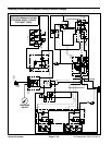
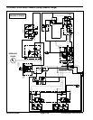
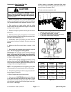
1. Test port G1 2. Relief valve
Figure 55
GM 4700--D
1
2
FRONT
Hydraulic
System