


Groundsmaster 4500--D/4700--DPage 7 -- 10Chassis
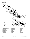
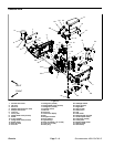
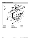
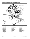
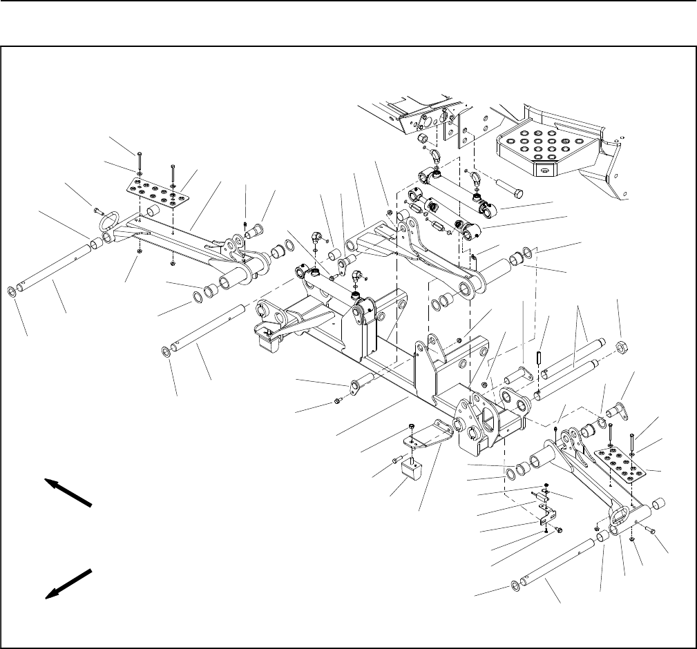
Lift Arms for Cutting Decks #1, #4 and #5
1. Flat washer
2. Flange nut
3. Lift arm (#1 deck)
4. Lift cylinder pin
5. Flange head screw
6. Flange nut
7. Cap screw
8. Lift cylinder (#4 and #5 decks)
9. Lift cylinder (#1 deck)
10. Thrust washer (2 used per arm)
11. Lock nut
12. Pivot pin
13. Slotted roll pin
14. Lift cylinder pin
15. Flange nut
16. Washer head screw
17. Skid plate
18. Lift arm (#4 deck)
19. Cap screw
20. Carrier pivot shaft
21. Front carrier frame
22. Grease fitting
23. Carriage b olt
24. Switch bracket
25. Deck position switch
26. Switch plate
27. Lock nut
28. Bumper support bracket
29. Bumper
30. Lift arm (#5 deck)
31. Lock nut
32. Grease fitting
33. Thrust washer
34. Flange bushing (2 used per arm)
35. Bushing (2 used per arm)
Figure 10
FRONT
RIGHT
2
3
5
4
7
8
9
10
11
26
27
28
6
15
14
13
12
17
16
32
22
29
30
24
23
20
19
18
25
31
1
10
17
19
14
20
20
4
4
2
1
6
7
19
21
22
5
33
33
33
35
35
35
34
34
34
10
10
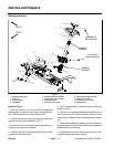
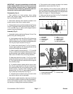
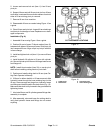
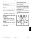
Removal (Fig 10)
1. Park machine on a level surface, lower cutting
decks, stop engine, engage parking brake and remove
key from the ignition switch.
2. Remove cutting deck assembly from lift arm (see
Cutting Deck O perator’s Manual).
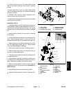
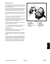
3. Ifliftarmforeitherdeck#4or#5(Fig.11)istobere-
moved, clean, label and remove hydraulic hoses from
the deck motor (Fig. 12). Place plugs or caps on open
fittings and hoses. Slide hoses out of the hose retaining
loop on the lift arm.
4. Remove lift cylinder pin (item 4) that secures hydrau-
lic lift cylinder to lift arm.