


Groundsmaster 4500--D/4700--DPage 6 -- 12Axles, Planetaries and Brakes
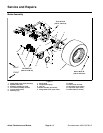
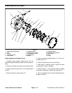
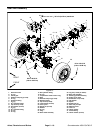
Planetary Wheel Drive Assembly
Figure 7
FRONT
RIGHT
1. Flange head screw (6 per planetary)
2. Splined brake shaft
3. Planetary assembly (2 used)
4. Front wheel assembly (2 used)
5. Lug nut (8 per wheel)
6. Retaining ring
7. Spring plate
8. Compression spring
9. Jam nut
10. Brake assembly (LH shown)
11. Flange head screw (4 per brake)
12. Gasket
13. Piston motor (2 used)
14. Flat washer (2 per motor)
15. Cap screw (2 per motor)
16. Brake cable (LH shown)
75 to 85 ft--lb
(102 to 11 6 N--m)
85 to 100 ft--lb
(116 to 135 N--m)
1
2
3
4
5
6
7
8
9
10
11
13
14
15
17
75 to 85 ft--lb
(102 to 116 N--m)
12
16
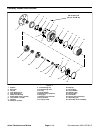
NOTE: Theplanetarywheeldriveassemblycanbeser-
viced with the planetary installed to machine (seePlane-
tary Wheel Drive Service in this section). Use the
following procedure to remove and install the planetary
wheel drive assembly from machine.
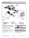
Planetary Wheel Drive Removal (Fig. 7)
1. Park machine on a level surface, lower cutting
decks, stop engine, engage parking brake and remove
key from the ignition switch.
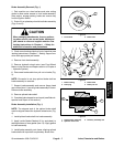
2. Drain oil from planetary wheel drive/brake assembly
(Figs. 8 and 9).
CAUTION
When changing attachments, tires or perform-
ing oth er service, use correct jacks, hoists and
jack stands to raise and support machine. See
Jacking Instructions in Chapter 1 -- Safety for
additional information and precautions.
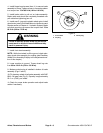
3. Chock rear wheels and jack up front of machine (see
Jacking Instructions in Chapter 1 -- Safety). Support ma-
chine with appropriate jack stands.