


Groundsmaster 4500--D/4700--D Hydraulic SystemPage 4 -- 19
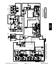
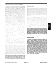
Lower Cutting Decks: Groundsmaster 4700--D
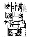
A four section gear pump is coupled to the piston (trac-
tion) pump. The third gear pump section supplies hy-
draulic flow to both the lift control manifold and the
steering control valve. Hydraulic flow from this pump
section is delivered to the circuits through a proportional
flow divider located in the fan control manifold. Maxi-
mum lift/lowercircuit pressure is limitedto 1600PSI (110
bar) by a relief valve (R1) in the lift control manifold. Lift
circuit pressure can be monitored at lift control manifold
test fitting G1.
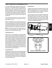
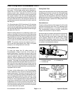
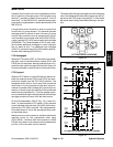
The Groundsmaster 4700--D has three (3) lift switches
to control the cutting decks (Fig. 12). The center switch
is for the five (5) center decks, the left switch controls the
left, rear deck (#6) and the right switch controls the right,
rear deck (#7) (Fig. 13).
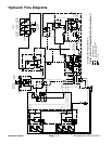
When the cutting decks are in a stationary position (not
raising or lowering), lift circuit flow from the third pump
section bypasses the lift cylinders through the lift control
manifold solenoid valve S1 and proportional relief valve
TS which are de--energized. Return flow from the man-
ifold is routed to the oil filter and traction charge circuit.
NOTE: The operator must be in the operator seat in or-
der to lower the cutting decks. Also, when in HI speed
(transport), the cutting decks will no t lower.
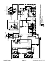
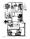
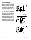
Cutting Deck Lower
To lower the center five (5) cutting decks on a
Groundsmaster 4700--D, the front of the center lift
switch is depressed. The switch acts as an input to the
TEC--5002 controller which then provides an electrical
output to s olenoid valves S1 and S6 in the lift control
manifold. These energized solenoid valves shift to allow
oil flow from the rod ends of the center five (5) deck lift
cylinders. The weight of the cutting decks cause the lift
cylinders toextend and the center decksto lower. An ori-
fice in the lift control manifold restricts oil flow from the
lift cylinders to control deck drop speed. Additionally, an
orifice in the junction manifold further controls the lower-
ingspeedofthe#1deck.
To lower a side cutting deck on the Groundsmaster
4700--D (deck #6 or #7), the front of the appropriate lift
switch is depressed. The switch acts as an input to the
TEC--5001 controller which then provides electrical out-
put to the appropriate solenoid valves in the lift control
manifold: S1, S3 and S4 for deck #6 or S1, S8 and S9
for deck #7. The energized solenoid valves shift to allow
pump flow to the barrel end of the deck lift cylinder and
a passage for oil from the rod end of the cylinder. The
cylinder extends to lower the sidecutting deck.An orifice
in the lift manifold restricts oil flow from the lift c ylinder
to control side deck drop speed.
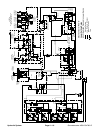
Cutting Deck Float
Cutting deck float allows the fully lowered cutting decks
to follow ground surface contours. On a Groundsmaster
4700--D, S6 (center decks), S4 (left deck #6) and S9
(right deck #7) are energized for deck float. These ener-
gized solenoids provide an oil passage to and from the
lift cylinders to allow cylinder and cutting deck move-
ment while mowing.
Counterbalance
Once the cutting decks are fully lowered, the lift control
manifold proportional relief valve (TS) maintains back
pressure (counterbalance) on the deck lift cylinders.
This counterbalance pressure transfers cutting deck
weight to the machine to improve traction.
A pressure sensor located in the hydraulic tube between
the front wheel and rear axle motors is used by the
TEC--5002 controller as an input to determine traction
circuit pressure. Based on this sensor input, a PWM
(Pulse Width Modulation) signal from the TEC--5002
controller isprovided to the proportional relief valve (TS)
to maintain counterbalance pressure.
1. Lift switch (#1 to # 5)
2. Lift switch (#6)
3. Lift switch (#7)
Figure 12
1
2
3
Figure 13
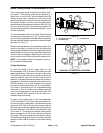
#4 #1 #5
#7#6
#3
#2
CUTTING DECK
GM--4700
LOCATIONS
Hydraulic
System