


Groundsmaster 4500--D/4700--D Page 7 -- 7 Chassis
IMPORTANT: A properly assembled and calibrated
traction pedal position sensor is critical to accurate
traction system response and for reliable sensor
life. Use care when removing, assembling and cali-
brating t he traction pedal position sensor.
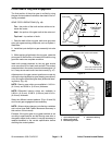
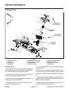
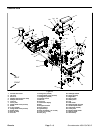
Disassembly (Fig. 5)
1. Park machine on a level surface, lower cutting
decks, stop engine, apply park ing brake and remove
key from the ignition switch.
2. Disconnect machine wire harness connector from
position sensor (item 29) on traction pedal.
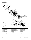
3. Disassemble traction pedal as needed using Figures
5, 6 and 7 as guides. When removing roll pins (items 11,
17, 21 and 28 in Fig. 5), make sure to support shaft to
prevent component damage.
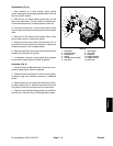
Assembly (Fig. 5)
1. Assemble traction pedal using Figures 5, 6 and 7 as
guides noting the following items:
A. Apply grease to both the OD and ID of the spring
retainer (item 23 in Fig. 5) before installation. Take
care tonot getgrease onthreads of spring shaft(item
19 in Fig. 5) or jam nut (item 9 in Fig. 5).
B. If traction pivot shaft (item 27 in Fig. 5) was re-
moved, apply grease to the shaft areas that will be
inside the bearings after assembly.
C. When installing roll pins (items 11, 17, 21 and 28
in Fig. 5), make sure to support shaft to prevent com-
ponent damage. Use a press to install roll pins. Also,
take care to not distort roll pins during assembly.
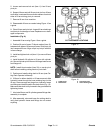
D. Make sure that roll pin (item 17 in Fig. 5) is fully
inside the butterfly groove of the hub (item 30 in Fig.
5). The roll pin should not contact the hub throughout
the operating range.
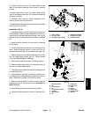
E. To install the traction pedal position sensor (item
29 in Fig. 5), align the slot on the end of the traction
pivot shaft with the slot in the position sensor. Hold
position sensor in position while installing standoff
spacers (item 16 in Fig. 5), capture plate (item 32 in
Fig. 5) and cap screws (item 33 in Fig. 5).
F. Leave the jam nut (item 9 in Fig. 5) loose so that
the position sensor can be calibrated.
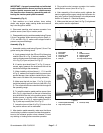
2. After traction pedal assembly, make sure that there
is no binding in pedal movement and also that pedal re-
turns to the centered position when released. Correct
any sticking or binding before machine operation.
3. Plug machine wire harness connector into traction
pedal position sensor (item 29 in Fig. 5).
4. After assembly of the traction pedal, calibrate the
traction pedal position sensor using the InfoCenter dis-
play (see Traction Pedal Calibration in the Adjustments
section of Chapter 5 -- Electrical System).
5. Make sure that jam nut (item 9 in Fig. 5) is tightened
after position sensor adjustment.
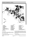
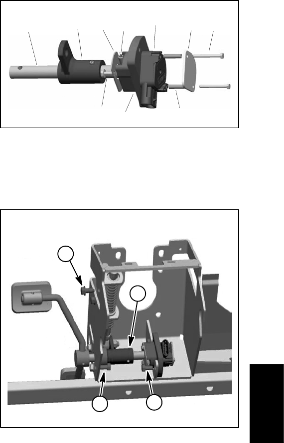
1. Pivot shaft
2. Pivot hub
3. Screw (2 used)
4. Cover plate
5. Roll pin
6. Hub
7. Position sensor
8. Spacer (2 used)
9. Capture plate
10. Cap screw (2 used)
Figure 6
2
3
6
8
9
1
5
7
4
10
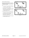
1. Traction pe dal assembly
2. Cap screw (4 used)
3. Screw (2 used)
Figure 7
1
3
2
2
Chassis