


Groundsmaster 4500--D/4700--D Page 5 -- 31 Electrical System
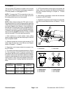
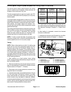
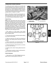
Hi/Low Speed, Engine Speed Request and Cutting Deck Lift Switches
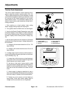
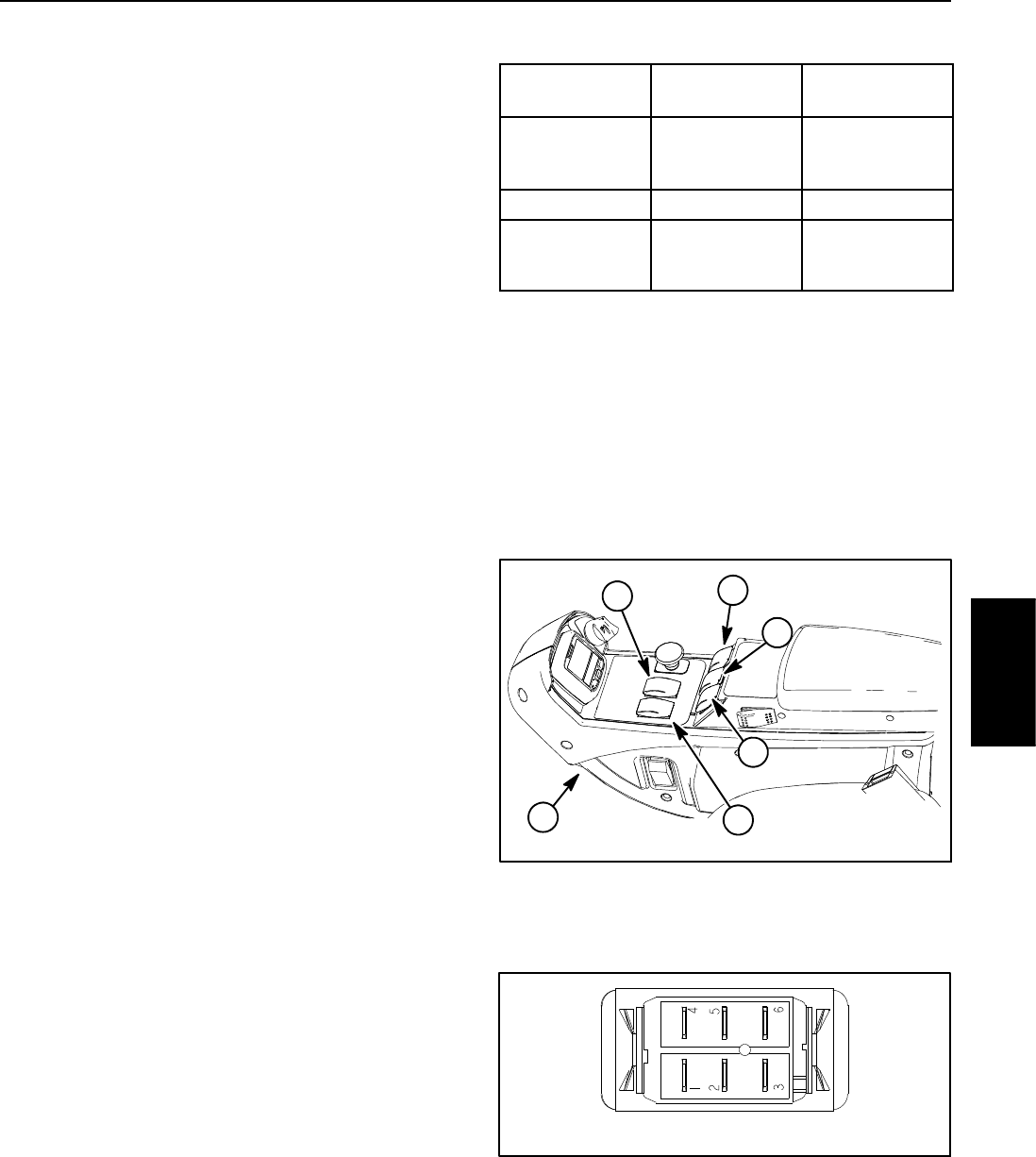
The Hi/Low speed, engine speed request and cutting
deck lift switches are all identical. These switches are
located on the console arm (Fig. 3 2).
The Hi/Low speed switch is used as an input for the TEC
controller to select either the Hi(transport) or Low(mow)
traction speed.
The engine speed request switch is used as an input for
the engine control unit (ECU)to raiseor lowerthe engine
speed. When the switch isdepressed and held inthe for-
ward position, the engine speed will increase. Con-
versely, when the rear ofthe switch isdepressed, engine
speed will decrease.
The cutting deck lift switches are used as inputs for the
TEC cont roller to raise or lower the cutting decks. When
the front of a lift switch is depressed, the controlled
decks will lower. When the rear of a lift switch is de-
pressed and held, the controlled decks will raise.
NOTE: To raise or lower the decks, the operator seat
has to be occupied. Also, to lower the cutting decks, the
traction speed has to be in Low (mow) range.
Testing
NOTE: Before disconnecting a switch for testing, the
switch and its circuit wiring should be tested as a TEC
electrical input using the InfoCenter Display (see In-
foCenter Display in this chapter). If input testing verifies
that the switch and circuit wiring are functioning correct-
ly, no further switch testing is necessary. If, however, in-
put testing determines that the switch and circuit wiring
are not functioning correctly, proceed with the following
switch testing procedure.
1. Park machine on a level surface, lower cutting
decks, engage parking brake and stop engine. Remove
key from ignition switch.
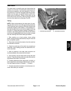
2. Remove consolearm covers togain access toswitch
that is to be tested (see Console Arm in the Service and
Repairs section of Chapter 7 -- Chassis).
3. Disconnect wire harness electrical connector from
theswitchthatistobetested.
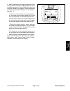
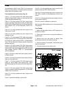
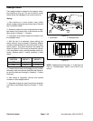
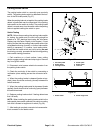
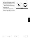
4. The switch terminals are marked as shown in Figure
33. The circuit logic of the switch is shown in the chart
below. With the use of a multimeter (ohms setting), the
switch functions may be tested to determine whether
continuity exists between the various terminals for each
position. Verify continuity between switch terminals. Re-
place switch if testing identifies a faulty switch.
SWITCH
POSITION
CLOSED
CIRCUITS
OPEN
CIRCUITS
FRONT OF
SWITCH
PRESSED
2+3
5+6
2+1
5+4
NEUTRAL NONE ALL
REAR OF
SWITCH
PRESSED
2+1
5+4
2+3
5+6
5. If switch tests correctly and circuit problem still ex-
ists, check wire harness (see Electrical Schematics and
Wire Harness Drawings in Chapter 9 -- Foldout Draw-
ings).
6. After testing is completed, connect wire harness
connector to the switch.
7. Assemble console arm (see Console Arm in the Ser-
vice and Repairs section of Chapter 7 -- Chassis).
1. Console arm
2. Engine speed switch
3. Hi/Low speed switch
4. Lift switch (#1 to #5)
5. Lift switch (GM4700 #7)
6. Lift switch (GM4700 #6)
Figure 32
1
4
5
6
2
3
Figure 33
BACK OF SWITCH
Electrical
System