


Groundsmaster 4500--D/4700--D Hydraulic SystemPage 4 -- 21
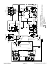
Raise Cutting Decks: Groundsmaster 4500--D
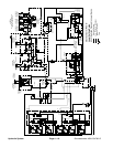
A four section gear pump is coupled to the piston (trac-
tion) pump. The third gear pump section supplies hy-
draulic flow to both the lift control manifold and the
steering control valve. Hydraulic flow from this pump
section is delivered to the circuits through a proportional
flow divider located in the fan control manifold. Maxi-
mum lift/lowercircuit pressure is limitedto 1600PSI (110
bar) by a relief valve (RV) in the lift control manifold. Lift
circuit pressure can be monitored at test fitting G1 on the
lift control manifold.
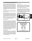
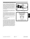
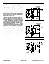
On the Groundsmaster 4500--D, a single lift switch on
theconsolearmisusedtoraiseandlowerthefive(5)
cutting decks (Fig. 14).
When the cutting decks are in a stationary position (not
raising or lowering), lift circuit flow from the third gear
pump section bypasses the lift cylinders through the lift
control manifold solenoid valve S5 and proportional re-
lief valve TS which are de--energized. Return flow from
the manifold is r outed to the oil filter and traction charge
circuit.
NOTE: The operator must be in the operator seat in or-
der to raise the cutting decks.
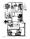
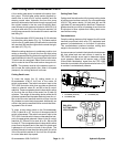
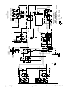
Cutting Deck Raise
To raise the five (5) cutting decks on a Groundsmaster
4500--D, the rear of the lift switch is depressed. The
switch actsas aninput tothe TEC --5002 controller which
then provides an electrical output to solenoid valve S5
in the lift control manifold. Energized solenoid valve S5
shifts to allow a passagefor oil flow to the rod endsof the
five (5) deck lift cylinders. The oil flow causes the lift cyl-
inders to retract and raise all of t he cutting decks. Two
(2) orifices in the junction manifold control the raising
speed of the #2 and #3 decks. The junction manifold ori-
fice leading to the #1 d eck is bypassed during deck rais-
ing.
Figure 14
1
2
1. Console arm 2. Lift switch
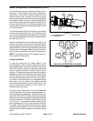
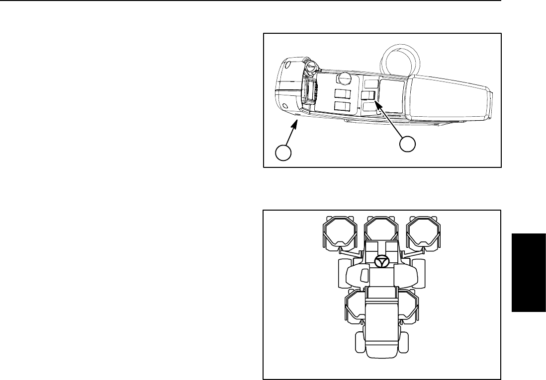
Figure 15
GM--4500 CUTTING DECK LOCATIONS
#4 #1 #5
#3#2
Hydraulic
System