


Groundsmaster 4500--D/4700--D Page 3 -- 23 Yanmar Diesel Engine
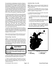
Groundsmaster models that are powered by adiesel en-
gine that complies with EPA Tier 4 emission regulations
are equipped with an exhaust system that includes a
diesel oxidation catalyst (DOC) and a diesel particulate
filter (DPF). These exhaust components require service
or component replacement at intervals identified in your
Operator’s Manual. Additionally, the exhaust assembly
uses two (2) temperature sensors and a pressure differ-
ential sensor which are used as inputs for the engine
ECU to monitor the operation of the exhaust system.
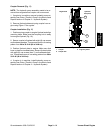
The diesel particulate filter (DPF) is cleaned periodically
through a regenerative process that is controlled by the
engine ECU (see Yanmar Engine: Models 30881 and
30882 in the General Information section of this
chapter). The InfoCenter display will identify the status
of DPF regeneration. At recommended intervals, DPF
reconditioning is necessary which will require exhaust
system disassembly, DPF removal and DPF recondi-
tioning by a company that has the necessary equip-
ment. Once the DPF has gone through the
reconditioning process, it can be re--installed in the ex-
haust system. Contact your Toro Distributor for informa-
tion on reconditioning the DPF.
The dieseloxidation catalyst (DOC)has a service life ex-
pectancy and requires replacement at recommended
intervals. Replacement of the DOC will require exhaust
system disassembly, removal of the existing DOC and
installation of the new DOC.
Refer to the Parts Catalog to identify individual compon-
ents for the e xhaust system on your Groundsmaster.
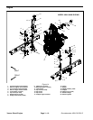
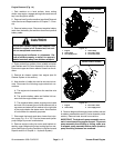
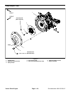
Removal (Figs. 19 and 20)
NOTE: TheexhaustsystemDPFandDOCcanbere-
moved from the exhaust system without removing the
entire exhaust from the engine. Certain engine service
procedures (e.g. rocker cover removal for valve clear-
ance adjustment) will require removal of the exhaust
system assembly.
CAUTION
The muffler and exhaust pipe may be hot. To
avoid possible burns, allow the engine and ex-
haust system to cool before working on the ex-
haust system.
1. Raise and support hood to gain access to exhaust
system. Allow engine and exhaust to cool before doing
any disassembly of exhaust system components.
2. Remove exhaust system components from the en-
gine as necessary using Figure 19 and 20 as guides.
Discard all removed gaskets (items 1 and 15 in Fig. 19
or item 6 in Fig. 20).
Installation (Figs. 19 and 20)
NOTE: Make sure that all exhaust system flanges and
sealing surfaces are free of debris or damage that may
prevent a tight seal.
1. Make sure to install new gaskets in place of all gas -
kets that were removed. Do not use any type of gasket
sealant on gasket o r flange surfaces.
2. Assemble all removed exhaust system components
usingFigure19and20asguides.
A. If exhaust sensors (items 7 and 8 in Fig. 19) were
removed, torque sensors from 19 to 29 ft--lb (25 to
40 N--m).
B. If exhaust pressure pipes (items 26 and 28 in Fig.
19) were removed, replace sensor gaskets (item 27)
on both sides of the pressure pipe fitting.
C. If DPF stiffeners (items 18, 19, 20 and 21 in Fig.
19) were loosened or removed, tighten fasteners
that secure stiffeners before tightening fasteners
that secure exhaust system to DPF stays.
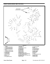
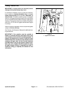
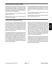
Figure 20
1. Engine
2. Exhaust pipe
3. Clamp assembly
4. Flange nut (4 used)
5. Exhaust flange
6. Exhaust gasket
1
2
3
4
5
6
Yanmar
Diesel Engine