


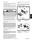
Groundsmaster 4500--D/4700--D Hydraulic SystemPage 4 -- 139
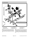
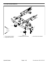
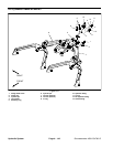
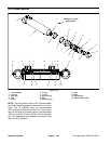
Removal (Fig. 116)
1. Park machine on a level surface, lower cutting
decks, stop engine, engage parking brake and remove
key from the ignition switch.
2. Read the General Precautions for Removing and
Installing Hydraulic System Components at the begin-
ning of the Service and Repairs section of this chapter.
3. To prevent contamination of hydraulic system during
manifold removal, thoroughly clean exterior of manifold.
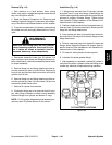
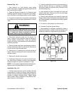
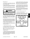
WARNING
Make sure that cutting decks are fully lowered
before loosening hydraulic lines from lift circuit
junction manifold. If decks are raised as hydrau-
lic lines are loosened, decks may drop unexpect-
edly.
NOTE: Upper three (3) hydraulic hoses on the front of
the junction manifold thread into manifold ports. Loosen
or remove opposite end of these hoses at lift cylinder fit-
tings to allow hose removal from the manifold.
4. Disconnect hydraulic lines from manifold and put
caps or plugs on open hydraulic lines and fittings. Label
disconnected hydraulic lines for proper assembly.
5. Remove hydraulic manifold from the frame using
Figure 116 as guide.
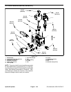
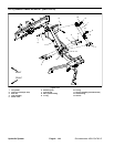
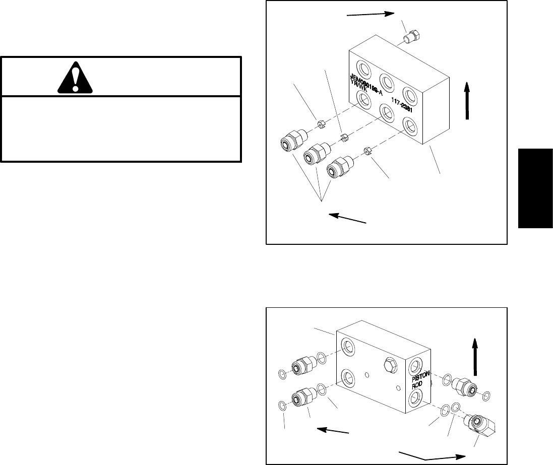
IMPORTANT: A flow control orifice is placed be-
neath several of the hydraulic fittings on the lift cir-
cuit junction manifold (Fig. 117). The manifold uses
two (2) different orifice sizes. If a fitting is removed
from the lift junction manifold and an orifice is in the
manifold port, make sure to remove orifice and label
its position for assembly purposes. Also note loca-
tion of groove in orifice for a ssembly purposes.
6. If necessary, remove fittings from manifold and dis-
card O--rings (Figs. 117 and 118).
Installation (Fig. 116)
IMPORTANT: When installing orifice in manifold,
make sure that orifice is flat in the base of the man-
ifold port. Manifold damage is possible if the orifice
is cocked in the cavity.
1. If fittings were removed from junction manifold, lubri-
cate and place new O--rings onto fittings. Install fittings
into manifold openings making sure that orifice is cor-
rectly placed beforethreading fitting intomanifold. Tight-
en fittings (see Hydraulic Fitting Installation in the
General Information section of this chapter). Refer to
Figures 117 and 118 for fitting installation torque.
2. Install hydraulic manifold to the frame using Figure
116 as guide.
3. Remove caps and plugs from fittings and hydraulic
lines. Properly connect hydraulic lines to manifold (see
Hydraulic Hose and Tube Installation in the General In-
formation section of this chapter).
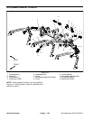
1. Manifold body
2. Orifice (0.055)
3. Orifice (0.030)
4. Straight fitting (3 used)
5. Zero leak plug
Figure 117
25 ft--lb
(34 N--m)
4
3
2
1
5
UP
20 ft--lb
(27 N--m)
3
FRONT VIEW
1. Manifold body
2. O--ring
3. Straight fitting (3 used)
4. O--ring
5. 90
o
hydraulic fitting
Figure 118
25 ft--lb
(34 N--m)
4
3
2
1
2
4
5
UP
REAR VIEW
Hydraulic
System