


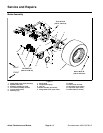

Groundsmaster 4500--D/4700--D Page 6 -- 7 Axles, Planetaries and Brakes
Brake Assembly Removal (Fig. 1)
1. Park machine on a level surface and raise cutting
decks to allow easier access to front brake assembly.
Stop engine, engage parking brake and remove key
from the ignition switch.
2. Drain oil from planetary wheel drive/brake assembly
(Figs. 2 and 3).
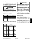
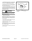
CAUTION
When changing attachments, tires or perform -
ing other service, use correct jacks, hoists and
jack stands to raise and support machine. See
Jacking Instructions in Chapter 1 -- Safety for
additional information and precautions.
3. Chock rear wheels and jack up front of machine (see
Jacking Instructions in Chapter 1 -- Safety). Support ma-
chine with appropriate jack stands.
4. Remove front wheel assembly.
5. Remove hydraulic wheel motor (see Front Wheel
Motors in the Service and Repairs section of Chapter 4
-- Hydraulic System).
6. Disconnect brake cable from pull rod on brake (Fig.
3).
NOTE: Be careful to not drop splined brake shaft as
brake assembly is removed.
7. Support brake assembly and remove flange head
cap screws (item 11) securing brake assembly to frame.
Remove brake assembly.
8. Remove splined brake shaft.
9. Complete brake inspection and repair (see Brake In-
spection and Repair in this section).
Brake Assembly I nstallation (Fig. 1)
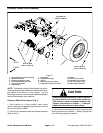
NOTE: The stepped end of the splined brake shaft
must be aligned toward the hydraulic wheel motor (Fig.
4).
1. Install splined brake shaft into brake assembly.
2. Apply Loctite Gasket Sealant #2 (or equivalent) to
sealing surfaces of new gasket (item 12). Apply gasket
to brake a ssembly.
3. Install brake assembly onto frame, aligning splined
brake shaft with input shaft on planetary wheel drive.
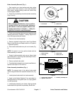
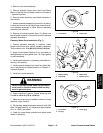
Figure 2
1. Front wheel 2. Brake drain
2
1
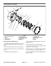
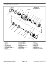
1. Brake housing
2. Drain plug
3. Brake cable
4. Brake pull rod
Figure 3
2
1
3
4
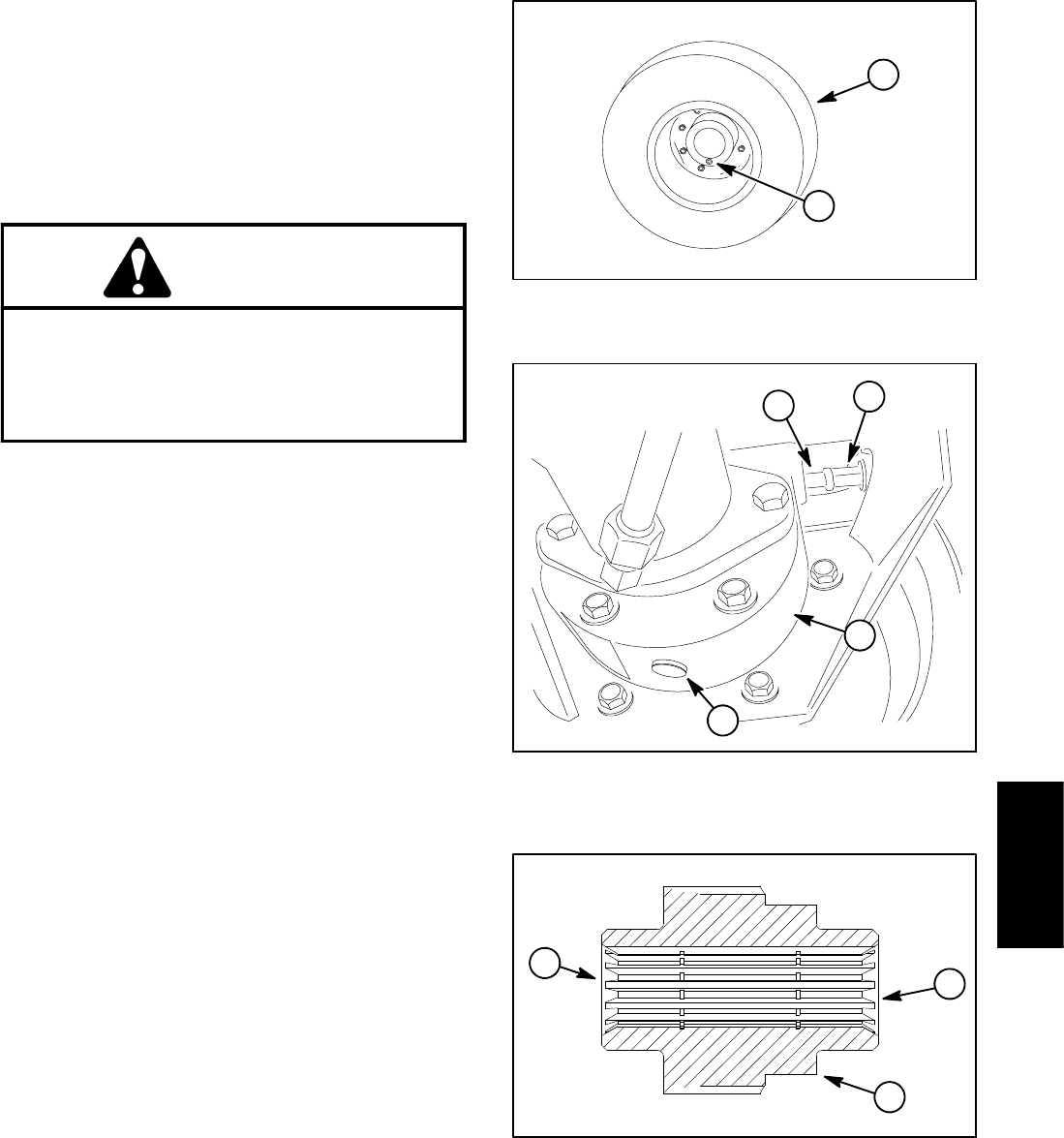
1. Splined brake shaft step
2. Hydraulic motor end
3. Planetary assembly end
Figure 4
3
1
2
Axles, Planetaries
and Brakes