


Groundsmaster 4500--D/4700--D Page 5 -- 43 Electrical System
Solenoid Coil Testing
1. Park machine on a level surface, lower cutting
decks, stop engine, engage parking brake and remove
key from the ignition switch.
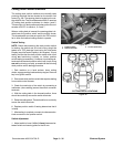
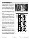
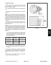
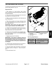
2. Locate hydraulic solenoid valve coil tobe tested (Fig.
51).
3. Disconnect wire harness connector from solenoid
valve coil.
NOTE: Prior to taking small resistance readings with a
digital multimeter, short the meter test leads together.
The meter will display a small resistance value (usually
0.5 ohms or less). This resistance is due to the internal
resistance of the meter and test leads. Subtract this val-
ue from from the measured value of the component you
are testing.
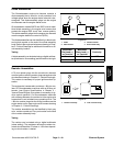
4. Using a multimeter (ohms setting), measure resis-
tance between the two (2) connector terminals on the
solenoid valve coil.
NOTE: Solenoid coil resistance should be measured
with solenoid at approximately 68
o
F(20
o
C). Resistance
may be slightly different than listed at different tempera-
tures. Typically, a failed solenoid coil will either be
shorted (very low or no resistance) or open (infinite re-
sistance).
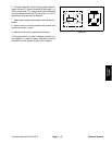
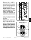
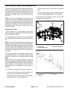
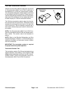
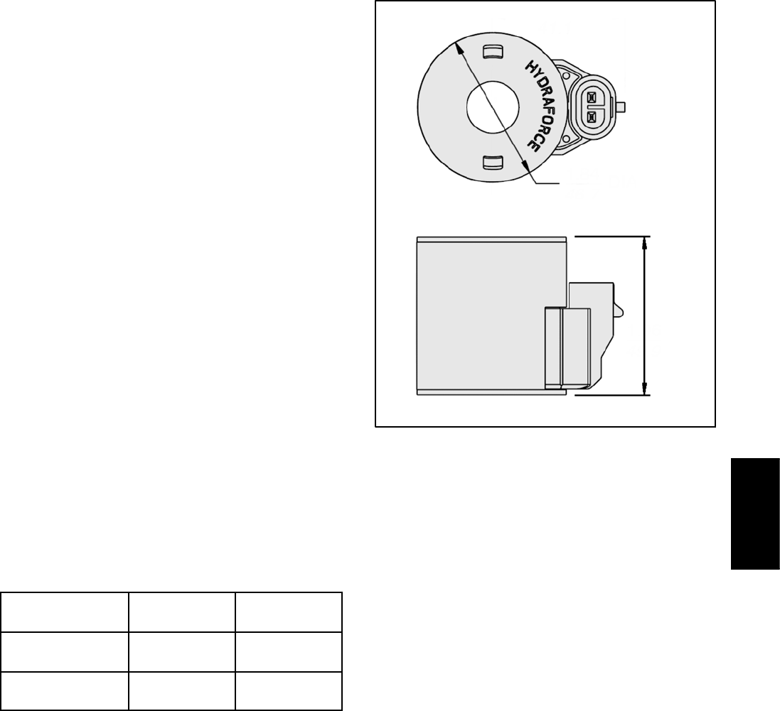
A. Ifcoilissecuredtovalvewithanut,identifycoilby
measuring the coil diameter and coil height (Fig. 52).
The correct resistance for the solenoid coil is identi-
fied in the table below.
COIL
DIAMETER
COIL
HEIGHT
COIL
RESISTANCE
1.84 in
(46.7 mm)
1.96 in
(49.9 mm)
7.1 ohms
1.41 in
(35.8 mm)
1.43 in
(36.3 mm)
8.8 ohms
B. The resistance of the solenoid valve coil in the HI/
LOW range control manifold (item 4 in Figure 51) is
7.1 ohms.
5. If solenoid coil resistance is incorrect, replace coil
(see appropriate control manifold information in the Ser-
vice and Repairs section of Chapter 4 -- Hydraulic Sys-
tem).
6. After testing is completed, connect wire harness
connector to the solenoid valve coil.
Figure 52
COIL
DIAMETER
COIL
HEIGHT
Electrical
System