


Telect, Inc. • USA +1.509.926.6000 • Mexico +1.52.33.3836.3700
Poland +1.48.713.239.100 • UK +1.44.1489.889500 • www.telect.com
Copyright © 2002 Telect, Inc., All Rights Reserved
Page 1-4
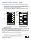
Each of the six possible patch modules (Model MDC-P72N) features 72 SC/APC cross-connect adapters for a total of 432 possible
subscriber cross connections. Model MDC-P72N-F100D includes the Model MDC-P72N connected to 100 ft (~30.5 m) of Dri-Flex™
OSP cable containing 250 µm fiber furcated to 900 µm loose tubing with an SC/APC connector.
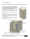
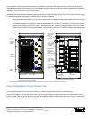
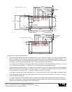
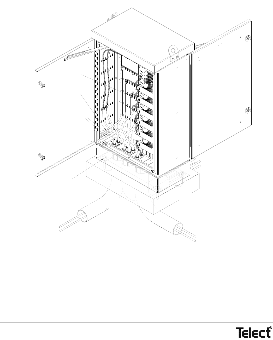
The following illustration shows a deployed cabinet along with a partially cabled rear compartment.
MDC-CB WITH REAR COMPARTMENT IN-CABINET SPLICING
The distribution and feeder OSP enter the cabinet at the floor of the rear compartment. The installer clamps the cable and breaks out
the fiber into 3-mm, radius-control (limited bend) loose tubing. The installer anchors feeder and distribution tubes along the cabinet’s
side wall and rear door.The tubes are guided to the top of the optional splice box located on the door.
The optional in-cabinet Telect Splice Box (Model MDC-SPLC) holds three pods of splice cassettes surrounded by a runway for the
loose tubing.
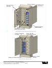
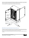
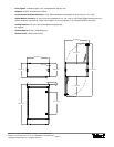
4-in. Conduits
Two Cable Entrance Clamps
Are Included With Cabinet
To Accommodate
Two Feeder Cables*
Concrete Pad
One Cable Entrance Clamp
For a Distribution Cable*
Is Included With The
Patch Module
* Cable Entrance Clamps Accommodate
Cable Between 3/8 in. & 1-1/5 in.
In Dia. Additional clamps
Anchors & Conduit Are
Not Included With Cabinet.
Rear of Patch Module
Bar for Grounding
Single-Armored Cable
are available.