


Telect, Inc. • USA +1.509.926.6000 • Mexico +1.52.33.3836.3700
Poland +1.48.713.239.100 • UK +1.44.1489.889500 • www.telect.com
Copyright © 2002 Telect, Inc., All Rights Reserved
Page 4-5
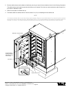
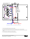
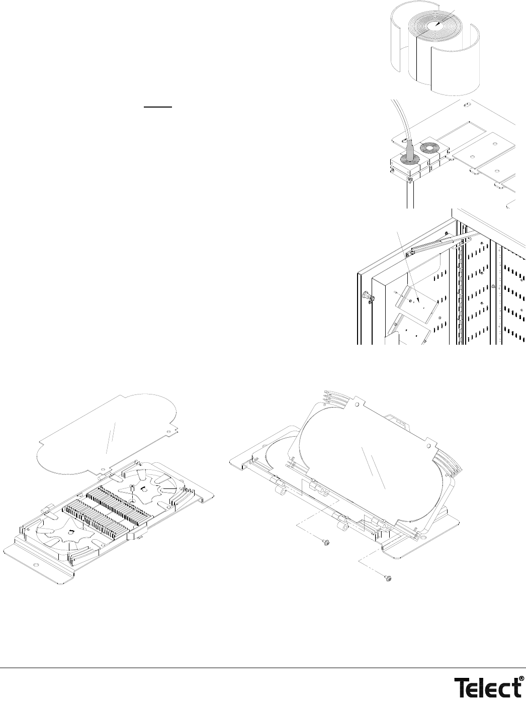
5. Carefully remove buffer/subunit tubes from the 15-foot unsheathed end and place fiber
into 3-m radius-control (bend limiting) loose tubing. Use heat-shrink tubing to hold loose
tubing to sheathed end of feeder cable.
6. Measure diameter of cables and remove and discard that much from the interior of the ca-
ble clamp’s leaf bundle equal to the diameter of the cables. The remaining leaves will be
used between the clamp halves and the cable.
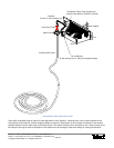
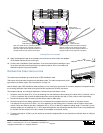
7. At end of heat-shrink on cable, loosely
secure the leaf bundle(s) and clamp
halves to the cable(s), as shown in the illustration at the start of this procedure.
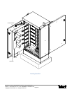
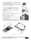
8. Place cable entrance dock at bottom of cabinet and slip on cable clamps, as
shown on the right.
If you have only one feeder cable to install, you must use the other cable clamp to
fill out the slot.
9. Hold down or temporarily fasten dock to cabinet.
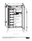
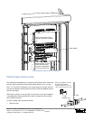
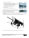
10. Remove top cassette holder on splice box, as shown on the right. Save the two
nuts
11. Place holder on a splice cart or other convenient work surface.
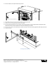
12. Remove and save two screws near center of holder.
13. Remove transparent cover of cassette.
14. Use the two screws to secure the first (bottom most) splice cassette to the brack-
et, as shown in the next illustration.
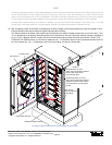
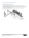
15. Add more cassettes, as shown.
Each plastic cassette has molded in pairs of male and female hinge halves. The
female part of the hinge of the top cassette mates with the male part on the cas-
sette below. Two collar screws, supplied with each cassette, secure the hinge.
Bushing Leaf
Solid Core (Discard)
Brackets Will Hold a Pod
of Splice Cassettes to
the Splice Box
Installing Cassettes
First Cassette Adding Cassettes