


Telect, Inc. • USA +1.509.926.6000 • Mexico +1.52.33.3836.3700
Poland +1.48.713.239.100 • UK +1.44.1489.889500 • www.telect.com
Copyright © 2002 Telect, Inc., All Rights Reserved
Page 4-8
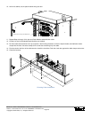
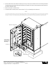
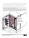
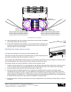
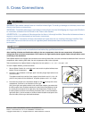
17. Feed connectorized feeder interface fiber through loose tubing.
18. Secure ends of both feeder tubes at opposite entrances to the cassette, as shown in the following illustration.
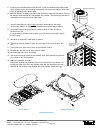
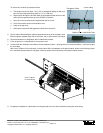
19. Route fiber around the perimeter, trim excess, slip on heat-shrink fusion splice sleeve, and splice all fibers from the installed
tubes.
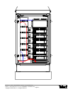
20. Record terminations on designation label included with cassette.
21. Finish all feeder splices before installing and splicing distribution fiber.
T
ray No
.
:
Po
s
.De
sig
n
a
t
io
n
1
2
3
4
5
6
7
8
9
10
1
1
12
1
3
1
4
1
5
1
6
1
7
1
8
1
9
2
0
2
1
22
23
24
Tra
y
N
o.:
Pos. Design
a
tion
1
2
3
4
5
6
7
8
9
1
0
11
1
2
13
14
15
16
17
18
19
2
0
21
22
23
24
T
ray No
.:
Pos. De
sig
n
atio
n
1
2
3
4
5
6
7
8
9
10
11
12
13
14
15
16
17
18
19
2
0
21
22
2
3
24
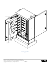
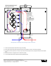
Feeder Adapters
Patch Module
Fiber From Right End of
Each Cassette to Patch
Panels Must Be in 3-mm,
Radius-Control Loose
Tubing
All Fiber From Cable Entrance to the Left
End of Each Cassette Must be in 3-mm
Radius- Control Loose Tubing
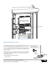
Each Fiber From
Right End of Each
Cassette to the
Feeder Adapters
Must Be in 3-mm,
Radius-Control Loose
Tubing
Left En
d
Ri
g
h
t
E
n
d
FRONT
REAR
Routing Feeder & Distribution Loose Tubing (Left View of Rear Door)