


Telect, Inc. • USA +1.509.926.6000 • Mexico +1.52.33.3836.3700
Poland +1.48.713.239.100 • UK +1.44.1489.889500 • www.telect.com
Copyright © 2002 Telect, Inc., All Rights Reserved
Page 3-2
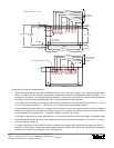
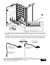
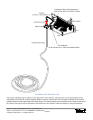
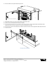
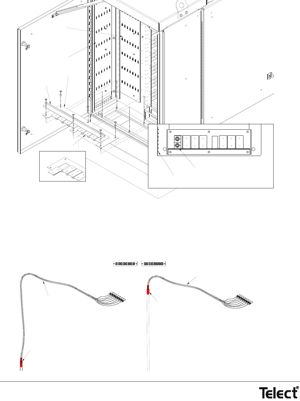
4. Use the next illustration to calculate the length of cable(s) required between the splice box (vault or aerial enclosure) and the
feeder adapters near the top of the cabinet’s rear compartment. Use heat-shrink tubing to secure the loose tubing at the end of
the cable(s).
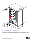
The illustration shows approximate lengths of exposed subunits/buffers to accommodate the 900 µm fiber between the breakout
and the SC/APC connectors. Any breakout length between 15 in. and 50 in. will fit: a short breakout length would place the
breakout near the top of the feeder tie-down wall; conversely longer lengths would be tied down closer to the cable entrance.
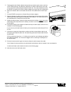
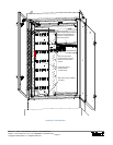
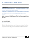
Cable Entrance Dock
Cover Plates
Chock Bar
Preferred Locations of Feeder Cable Clamps
Tie-Down Lance on Feeder Tie-Down Wall
Top View of Cabinet's Rear Floor
Feeder Tie-Down Wall
Distribution Tie-Down Wall
OSP Feeder Cable From Splice Enclosure (Dressed Out)
16
9
8
Breakout from Cable to
Subunits/Buffers Near Bottom
of Rear Compartment
Breakout from Cable to
Subunits/Buffers Near Top of
Rear Compartment
Subunit/Buffer Between
Breakout and Connector:
~40 in. for Connector 16
to ~50 in. for Connector 1
1
Subunit/Buffer Between
Breakout and Connector:
~15 in. for Connector 16
to ~25 in. for Connector 1
Feeder Adapters
(Rear Compartment View)