


5. Cross Connections
Telect, Inc. • USA +1.509.926.6000 • Mexico +1.52.33.3836.3700
Poland +1.48.713.239.100 • UK +1.44.1489.889500 • www.telect.com
Copyright © 2002 Telect, Inc., All Rights Reserved • Telect Publication 131220 A0
WARNING
!
WARNING! Fiber cables transmit laser or invisible infrared light. To avoid eye damage or blindness, never look
directly into fibers or connections.
WARNUNG! Faserkabel übertragen unsichtbares Infrarotlicht. Um eine Schädigung der Augen oder Blindheit
zu vermeiden, schauen Sie nicht direkt in die Fasern oder Stecker.
ADVERTENCIA ! Los cables de fibra transmiten luz láser o infrarroja invisible. Para evitar lesiones oculares o
ceguera, nunca mire directamente a las fibras o conectores.
AVERTISSMENT ! Les câbles à fibres transmettent un rayon laser ou une lumière infrarouge invisible. Pour
éviter toute lésion occulaire ou cécité, ne regardez jamais directement dans les fibres ou dans les
connecteurs.
ALERT
!
ALERT! This product must be installed and maintained by qualified technicians.
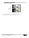
After installing all feeder and distribution cabling in the rear compartment, close the rear compartment. All subscriber
changes are done in the front compartment. First, however, the high-intensity feeder signals needs to be split before cross
connecting to the distribution.
Telect Splitter Modules are installed, interconnected to the incoming feeder fiber, and cross connected to distribution fiber in the front
compartment. After installing OSP cable, the rear compartment need not be re-opened.
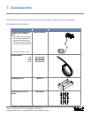
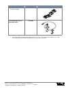
Telect manufactures four Splitter Module configurations for this cabinet: 1 x 4, 1 x 8, 1 x 16, and 1 x 32.
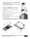
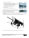
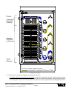
To install a Splitter Module, proceed as follows:
1. Start at Splitter Position 18 on the right
and insert module in splitter bulkhead near
bottom of front compartment.
2. As shown in the illustration on the right, push in the two plunger-style latches to se-
cure the module.
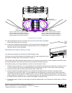
The splitter module has one blue 2-mm jumper for the feed-in and 4, 8, 16, or 32
yellow 2-mm jumpers for the distribution. All splitter jumpers are 2.1 m in length.
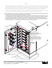
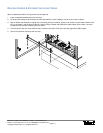
3. Route the blue jumper to the first feeder adapter on the left
at the top of the front
compartment, as shown in the illustration on the right.
Going from right most splitter module to left most feeder adapter guarantees that
the blue jumpers from all splitter modules will neatly fit the same pathway around
the routing arcs and spools in the right half of the compartment. Prefer to route
the blue jumpers as shown in the following illustration, that is, around the bottom,
right most spool, up to the nearest arc, down around the bottom most spool to the
left of the other, and on up to the feeder bulkhead.
Installing Splitter Module
Connecting to Feeder