


Telect, Inc. • USA +1.509.926.6000 • Mexico +1.52.33.3836.3700
Poland +1.48.713.239.100 • UK +1.44.1489.889500 • www.telect.com
Copyright © 2002 Telect, Inc., All Rights Reserved
Page 3-6
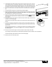
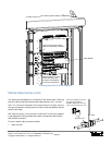
The cable clamp, shown on Page 3-1, is the same type used to secure distribution cable. One cable clamps is provided. An addition-
al cable clamp may be required to fill out the two-position entrance slot. (See “Standard Accessories” on Page 7-1.)
The fan-out block allows transition from the 250 µm fiber in subunits to individual connectorized fiber strands in 900 µm transparent
tubes. Telect terminates the connector at adapter ports at the rear of the patch module.
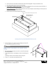
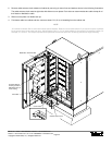
To install a Patch Module with distribution cable, proceed as follows:
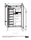
1. Open rear door.
2. Remove cable entrance dock at bottom of the cabinet, shown on Page 3-2.
3. Slide-out cover plate over distribution stub up(s).
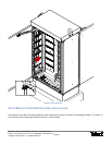
Patch Modules will be installed from the top position (Patch Module 1) to the bottom (Patch Module 6). Unless otherwise direct-
ed by operating company guidelines, prefer to start with the first distribution stub-up farthest from the patch module rack.
Determine the length of the subunit breakout between the fan-out blocks on the edge of the patch module and the sheathed ca-
ble. The end of the sheathed cable will be either clamped and tied down on the distribution tie-down wall or
at the cable clamp
on the cable entrance dock.
NOTE
Telect only breaks out about 7 in. (~175 mm) of subunit. This would be for the shortest breakout from a cable clamp near the
center of the cable entrance dock to Patch Module 6. The longest breakout would be about 64 in (~1600 mm) between a cable
clamp near the left wall (viewed from the front of the cabinet) to Patch Module 1.
All cables entering the cabinet directly below the patch module rack need to be broken out at the cable clamp. The cable is not
flexible enough to manipulate it below the rack and around to the distribution tie-down wall. Conversely, all cables entering the
cabinet directly below the distribution tie down wall should be extended up the tie-down wall and tied down just below a conve-
nient breakout point. (Refer to the illustration on Page 1-4.)
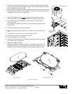
4. Breakout subunits, heat shrink breakout, and then feed the opposite end of the cable into the distribution stub-up conduit.
5. Move the cable clamp down to approximately where the cable will enter the bottom of the cabinet.
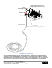
NOTE
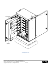
Before connecting, splicing, storing, or parking distribution pigtails at the home, office, or node, install the Patch Module in the
cabinet, as detailed in the following procedure. Refer to the following illustration.
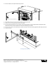
6. If necessary, provide temporary strain relief while handling and installing Patch Module by, for example, loosely tying down the
cable at a convenient lance along a tie-down wall.
7. Swing out hinged bulkhead from patch module’s anchor plate so that bulkhead fits through rack into front compartment. Then,
secure anchor plate to partition wall using three acorn nuts provided.
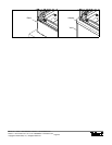
8. Secure cable and subunit to distribution cable tie-down wall. Use plenty of cable ties.
Don’t use cable ties closer than about 1 ft (~300 mm) from the floor of the cabinet until all feeder and distribution cables are in-
stalled. You’ll need some wiggle room for re-installing the cable entrance dock.
9. At bottom of cabinet, adjust position of cable clamp in relationship to the cable entrance dock. Don’t secure the entrance dock
until all scheduled distribution cables and Patch Modules are installed.