


Telect, Inc. • USA +1.509.926.6000 • Mexico +1.52.33.3836.3700
Poland +1.48.713.239.100 • UK +1.44.1489.889500 • www.telect.com
Copyright © 2002 Telect, Inc., All Rights Reserved
Page 4-9
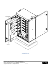
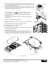
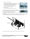
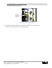
22. Apply the designation label to the cassette cover and connect ends of fiber into adapters
on the feeder interface shown on the right.
23. Continue with “Distribution Cable Installation” in the next section before installing the pod
on the door and before securing tubing to the cabinet and door. Do not mix feeder and
distribution splices in the same cassette.
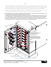
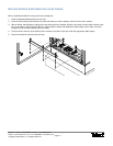
DISTRIBUTION CABLE INSTALLATION
The cabinet accommodates up to 432 strands of OSP distribution cable.
Telect does not include cable clamps for the distribution cable. The cable clamps are the same
type used for the feeder cables. See “Accessories” on Page 7-2.
Like the feeder cable, OSP distribution cable can be dry or wet, armored or unarmored. To connect to adapters in the patch module,
the incoming distribution fiber needs to be spliced to fiber strands with SC/APC connectors.
The breakout, splicing, and routing of distribution is similar to that of the feeder. In brief,
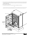
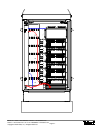
1. As before, remove at least 15 ft (~2.5 m) of sheathing from the distribution cable entering the cabinet. More, if desired, in 8½ ft
(~2.5 m) increments. Also remove the buffer/subunit tube covering the fiber and slip on 3-mm, radius control loose tubing.
2. Heat shrink tubing to cable at entrance dock and then attach a cable clamp
3. Check the length of loose tubing required for the run between the cassette and the fan-out block on the patch module.
The distance will vary from 6¾ to 9¾ ft (~2 to 3 m) depending on the starting point on the door and the location of the patch
module. Check the distance and add in multiples of 8½ ft (~2.5 m), if desired, to determine tubing length. For the fiber, you will
need this length plus an additional 4 ft (~1.25 m) beyond that point for the unprotected strands which will be in the cassette and
for the fiber from the entrance of the fan-out block to the adapter on the patch module.
4. For each loose tube of 12 fibers, you will need a fan-out block to adapt the fiber in one loose tube to individual fibers in a 900 µm
loose tubes.
1
2
3
4
5
6
7
8
9
10
11
12
13
14
15
16
17
18
19
20
21
22
23
24
1
2
3
4
5
6
7
8
9
10
11
12
13
14
15
16
17
18
19
20
21
22
23
24
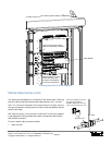
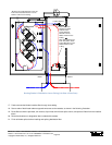
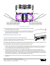
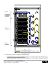
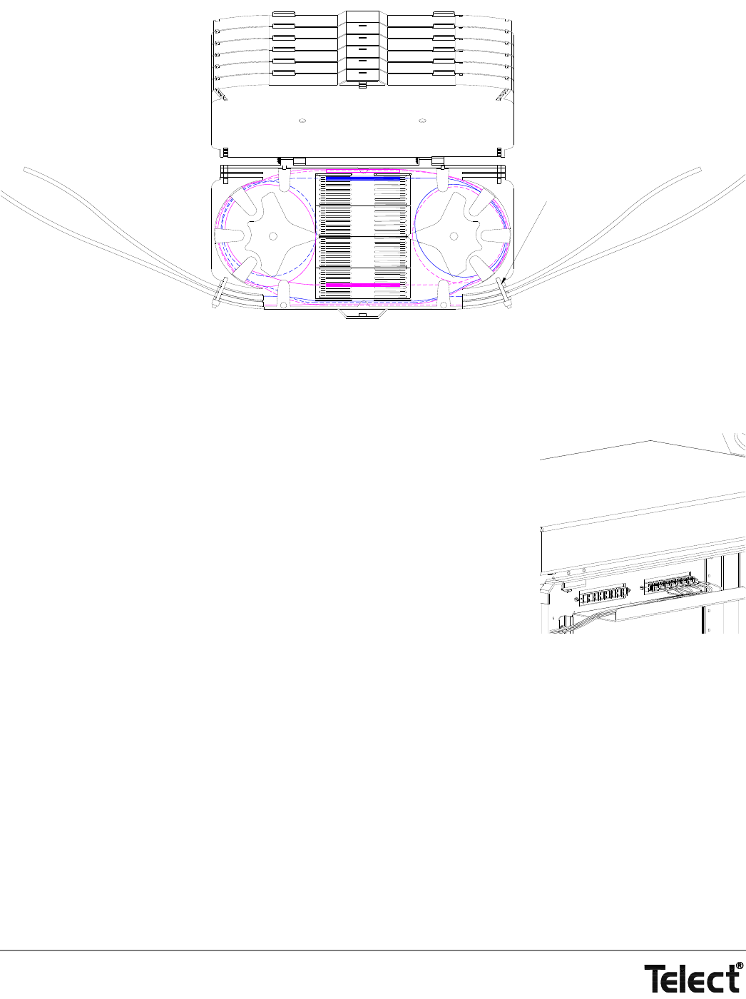
To/From
Cable Entrance
To/From
Feeder Interface
Cable Ties at
Cassette Entrances
Fiber from cable entrance to Splice Positions 1
through 12 will be at the right end of the splice.
Fiber from cable entrance to Splice Positions 13
through 24 will be at the left end of the splice.
Fiber from feeder interface to Splice Positions 1
through 12 will be at the left end of the splice.
Fiber from cable entrance to Splice Positions 13
through 24 will be at the right end of the splice.
Routing Fiber in a Cassette