


Ridge Tool Company Elyria, Ohio U.S.A www.seektech.com 7
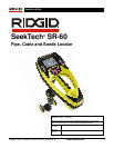
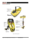
SeekTech SR-60
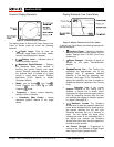
Common Display Elements
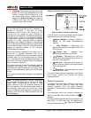
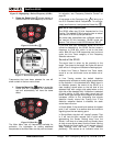
Figure 4: Common Display Elements
The display screen in Active Line Trace, Passive Line
Trace or Sonde mode will show the following
features:
•
Signal Angle: Field tilt from the
horizontal; angle toward the field’s center;
numeric value displayed in degrees.
•
Battery Level – Indicates level of
remaining battery capacity.
•
Measured Depth/Distance – Displays
the measured depth when receiver is
touching the ground directly over signal
source. Displays computed distance when
the antenna mast is pointed at a signal
source in some other manner. Displays
feet/inches (U.S.A. default) or meters
(European default).
• Mode– Icon for Sonde
, Line Trace ,
Power (Passive Line Trace)
, or Radio
Frequency
mode.
• Frequency – Shows current frequency
setting in hertz or kilohertz.
• + Crosshairs (Map Center) - shows
operator’s position relative to the target
center.
Display Elements: Line Trace Mode
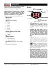
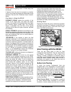
Figure 5: Display Elements (Line Trace Mode)
In Active Line Trace Mode, the following features will
also be displayed:
•
Proximity Signal – Numerical indication
showing how close the signal source is to the
locator. Displays from 1 to 999. (Line Trace
modes only)
•
Signal Strength – Strength of signal as
sensed by the lower Omnidirectional
antenna.
•
Tracing Line – The Tracing Line
represents the approximate axis of the
detected field. It represents detected
distortion in the field by appearing less
focused. (See page 33 for information on
setting the sensitivity and how to enable or
disable the distortion response in the Tracing
Line.)
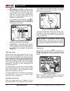
•
Distortion Line If the normal
distortion response of the Tracing Line is
disabled, a second line is shown, which
represents the signal from the upper antenna
node. By comparing the two lines, the user
can estimate the degree of distortion present
in a signal. (See page 35.)
•
Guidance Arrows The Guidance
Arrows serve to steer the operator toward the
center of the detected field, by showing when
the signals reaching the left and right
Guidance Antennas are out of balance or
equal. The two signals are equal when
crossing the center of an undistorted field. If
the signals are unequal, the Guidance
Arrows show which way the field appears to
be relative to the receiver.
•
mA Current Strength – Proportional to
current on the line. Switches to Signal Angle
when Signal Angle is greater than 35°.