


18 www.seektech.com Ridge Tool Company Elyria, Ohio U.S.A
SeekTech SR-60
overcome resistance and inject more
current onto the line.
e. Re-locate the ground connection for a
better circuit. Ensure there is enough
contact (ground stake is sufficiently
deep) especially in dryer soils.
f. In extremely dry soil, wetting the area
around the ground stake will improve the
circuit. Be aware the moisture will
dissipate and evaporate, reducing the
quality of the circuit over time.
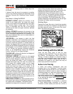
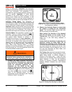
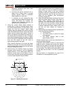
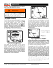
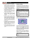
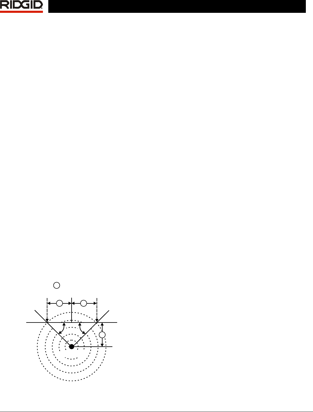
5. Using the numeric Signal Angle Indicator is
another way to check for distorted signals. Move
the SR-60 perpendicularly to both sides of the
traced line until the numeric Signal Angle
indicator reads 45 degrees. Be sure to keep the
lower Omnidirectional antenna node at the same
height, and the locator mast vertical. If there is
little or no distortion the traced line should be in
the middle and the distance to each 45 degree
point should be approximately the same on either
side. If the signal is undistorted, then the distance
from the line center to the 45° point is
approximately equal to the depth.
Note: Another technique is to move the same
distance to the right and left of the traced line,
say 24 inches (60 cm) and check that the Signal
Strength readings are similar.
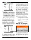
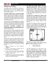
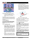
6. While tracing, the Proximity Signal and Signal
Strength should maximize, and the Measured
Depth minimize, at the same place where the
guidance arrows center on the display. If this is
not the case, the utility may be changing direction
or other coupled signals may be present.
Ground
45
°0°
45
°
45
°
45
°
45
°
A
A
A
=same distance
A
Energized Pipe
Figure 27: Checking for Distortion
7. Higher frequencies bleed over to adjacent utilities
more readily, but may be needed to overcome
breaks in tracer wires or go over insulating
couplers. If the line is ungrounded at the far end,
higher frequencies may be the only means to
make the line traceable. (See Informational
Locating, on page
39).
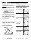
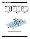
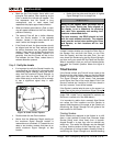
8. When using the transmitter inductively, be sure to
begin the locate about 30 feet (10m) away to
avoid “direct coupling” (also know as air
coupling). This occurs when the SR-60 picks up
the signal from the transmitter directly through
the air and not from the line to be traced. An
unrealistic Measured Depth reading when over
the line can also indicate air coupling is
occurring.
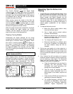
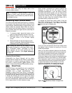
9. While tracing, the mapping display operates best
under the following conditions:
a. The line is level
b. The SR-60 Locator is above the target
utility elevation
c. The SR-60 antenna mast is held
approximately vertical
If these conditions are not met, pay close attention to
maximizing Signal Strength.
In general, if the SR-60 is used in a zone over the
target line within a sweep area of about two “depths”
of the line, the map will be useful and accurate. Be
aware of this when using the map if the target or line
is very shallow. The width of the useful search area
for the map can be small if the line is extremely
shallow.
See the section on Suppression on page
32 for
information on noise suppression options.