


Ridge Tool Company Elyria, Ohio U.S.A www.seektech.com 13
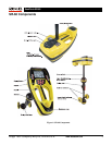
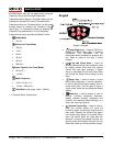
SeekTech SR-60
locator receiver is getting closer or further away from
the Sonde.
If desired, force the sound to re-center at a medium
level (in any mode) by pressing the Select Key during
operation. See also the “Directional Sound” section,
below.
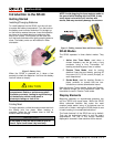
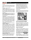
Key Items in Using the SR-60
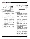
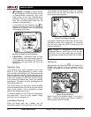
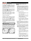
PROXIMITY SIGNAL reflects the proximity of the
locator to the target utility; the closer the locator
moves to the center of the detected field, the higher
the Proximity Signal number gets. The Proximity
Signal is calculated from the ratio of the signals
received at the lower and upper antennas, adjusted
for scalability.
SIGNAL STRENGTH represents the strength of the
field being detected by the lower antenna node of the
SR-60, converted mathematically for scalability. In a
clear and undistorted field, you can locate based on
Signal Strength alone.
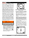
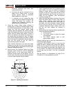
DISTORTION is the degree to which the field
detected is deformed. In an undistorted environment,
current on a long conductor produces a field which is
cylindrical, down the conductor. If multiple fields are
present, the detected field is pushed or pulled out of
shape and the different antennas will pick up different
field strengths. On the SR-60, distortion is reflected
by the Tracing Line growing unfocused instead of
sharp, or by disagreement among the Guidance
Arrows, Tracing Line, and Signal Strength.
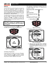
TRACING LINE indicates the direction and degree of
distortion in the detected field.
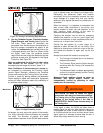
GUIDANCE ARROWS are driven by the signals
received at the guidance antennas of the SR-60.
When the fields detected by these side antennas are
equal, the arrows will center. If one is receiving a
stronger field signal than the other, the arrows will
point toward the probable center of the target
conductor. Moving in the direction indicated by the
arrows will bring you closer to the center of the
detected field. A small “guidance line” at the end of a
guidance arrow indicates the degree of alignment
with the conductor’s field. It will be at its maximum
length when correctly aligned with the conductor, with
the guidance antenna axis crossing the field at 90°.
Rotational guidance arrows on the perimeter of the
screen will indicate the direction you need to turn to
align with the detected conductor.
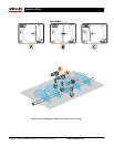
DIRECTIONAL SOUND from stereo speakers will let
you follow a line by sound, while staying visually alert
for nearby traffic or obstacles. The Sound Pointer
speakers are designed to be clipped to a jacket or
vest on either shoulder. Stereo sound from the
speakers will fade to the left or right. The louder side
indicates the direction toward the center of the
detected field. Sound will balance when over the
center of the line. The operator can stay centered on
the line using sound signals instead of the visual
cues on the screen. The SR-60 comes with clip-on
speakers designed to be attached to the left and right
shoulders of a safety vest for this purpose.
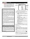
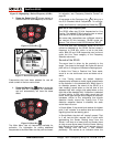
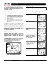
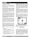
Shutting Down
Pressing the Power Key at any time during operation
will start a count-down of 3 seconds, during which the
shut-down tone will sound. At the end of the count-
down, the SR-60 will shut down.
Figure 19: Count-Down Screen (Shutting Down)
Line Tracing with the SR-60
There are two major ways to look for lines
underground with the SR-60. They are called Active
and Passive. The difference is that in Active Line
Tracing, a current is placed on a conductor using a
transmitter, and that specific signal is then sought for
using the locator. Passive tracing does not use a
transmitter and seeks for any signal that may be
picked up at particular frequencies.
Active Line Tracing
In active line tracing, underground lines are
energized with a Line Transmitter. This active signal
is then traced using the SR-60. A Line Transmitter is
different from a Sonde in that it is used to energize a
conducting target line, rather than acting as a target
for a locate itself, the way a Sonde does. Line
transmitters energize lines by direct connection
with
clips, or by directly inducing the signal using a clamp
,
or by inducing the signal using inductive coils
built
into the transmitter.
Direct Connect Mode: The transmitter is attached
by direct metal-to-metal connection to the target
conductor at some access point such as a valve, a