


Ridge Tool Company Elyria, Ohio U.S.A www.seektech.com 35
SeekTech SR-60
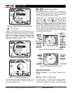
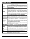
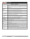
Menu Tree
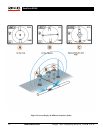
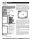
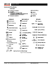
The following figure shows options and controls built
into the SR-60 menus.
Activated Frequencies
Sonde
512
Line Trace
126 Hz, 1 kHz, 8 kHz, 33 kHz, 93
kHz, 262 kHz
Power
60^9 (450 Hz), <4 kHz
Radio
L( 4-15 kHz), H (15-35 kHz)
OmniSeek
<4 kHz + 4-15 kHz + 15-35 kHz
Depth Units
Feet, Meters
Backlight
On/Off/Auto
Auto Shutdown
1 HR, Off
LCD Contrast
Increase/Decrease
Display
Elements
Sonde Mode Trace Mode
*=Line Trace
Display Only
¾ Watermark
¾ Signal Focus Setting
¾ No-Signal Indicator
¾ Sound Signals
¾ Center Signal Strength*
¾ Signal Strength
¾ Signal Angle Indicator
¾ Distortion Line Response*
(Hi, Med, Low)
¾ Tracing Line Distortion *
¾ Sound Mute > 99’
¾ Guidance Arrows*
Frequency
Selection
¾ SimulTrace™: 512 Hz
+ 33 kHz
¾ Sonde: Custom Frequencies,
16, 512, 640, 850, 8k, 16k, 33k
¾ Line Trace: Custom
Frequencies, 128 Hz, 1 kHz, 8
kHz, 33 kHz, 51 kHz, 93 kHz,
93 kHz-B, 200 kHz, 262 kHz
¾ Power: Custom Frequencies,
50 Hz, 60 Hz, 100 Hz,
120 Hz, 50^5 (250 Hz), 60^5
(300 Hz), 50^9(450 Hz), 60^9
(540 Hz), <4kHz
¾ RF: L (4-15 kHz), H (15-35
kHz)
¾ OmniSeek: <4kHz + 4-15
kHz + 15-35 kHz
Information
Menu
Restore Defaults, Clear Custom
Frequencies, Cancel
Figure 64: SR-60 Menu Tree
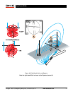
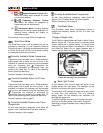
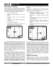
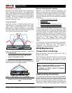
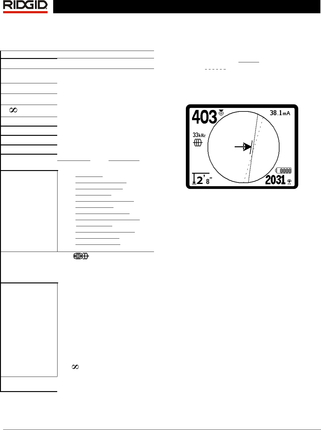
Operating With the Distortion Line
If the Tracing Line’s distortion response (blurring) is
disabled, the detected field will be shown with two lines,
one solid (the Tracing Line
) and one dashed (the
Distortion Line
). (The dashed Distortion Line can
be separately selected to be on or off in the Display
Elements menu). The dashed Distortion Line is the
signal as seen by the upper antenna node and the solid
Tracing Line is the signal as seen by the lower node.
Figure 65: Screen Display with Distortion Line
(Line Trace Mode)
The Tracing Line without the dynamic distortion
response (blurring) still represents the location, and the
direction, of the signal being traced. It still reflects
changes in direction of the target utility. And it helps
recognize signal distortion, when compared to the
dashed Distortion Line — if something is interfering with
the signal and distorting its shape, the Distortion Line
could be significantly offset or skewed.
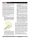
The Tracing Line represents the signal received by the
lower antenna node. The Distortion Line represents the
signal received by the upper antenna node. If these two
do not align, or they do not reflect the same information
as the Guidance Arrows about where the center of the
field is, then the operator knows he is looking at some
kind of distortion.
The two lines may also move randomly if a weak signal
is being received, indicating that the locator circuit needs
to be improved.
The balance of the Tracing Line and the Distortion line
combine to give the operator much the same information
as the Tracing Line with its distortion response enabled,
but in a different graphical form. Advanced operators
may find this more useful in discriminating the primary
signal from the impact of distortion.