


36 www.seektech.com Ridge Tool Company Elyria, Ohio U.S.A
SeekTech SR-60
Informational Locating
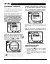
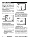
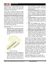
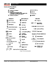
The normal shape of a field around a long conductor
such as a pipe or cable is circular (cylindrical in three
dimensions). When over the center of a circular field,
the operator can observe the following indicators:
• Maximum Signal Strength
• Maximum Proximity Signal (Line Trace
Mode)
• Centered Tracing line with minimized
distortion
• Guidance arrows centered, agreeing with
Tracing line
• Minimum Measured Depth
• Sound pitch and volume will increase until
they maximize over the target utility.
Figure 66: Over a Circular Field
The experienced operator learns to “see” the ground
situation by knowing how the different pieces of
information provided by the SR-60 relate to each
other. While a simple straightforward locate of a
circular field is fast and easy, tracing a line which is
near other large conductors such as power lines,
phone lines, gas mains, rebar, or even buried scrap
metal can lead to questions which can only be
correctly answered by taking all the available
information into account.
By comparing the Guidance Arrows, the Tracing Line,
Signal Strength, Signal Angle, Measured Depth, and
Proximity Signal, an operator can see which way the
field is being distorted. Comparing the field
information with an educated view of the ground,
noticing where transformers, meters, junction boxes,
manholes, and other indicators are located can help
in understanding what is causing field distortion. It is
important to remember, especially in complex
situations, that the only guarantee of the location of a
particular line or pipe is visual inspection, such as by
potholing.
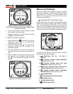
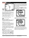
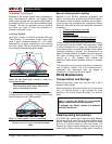
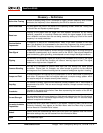
Compound or complex fields will produce different
indications on the SR-60 that will show what is
happening. Some examples might be:
• Disagreement between guidance arrows,
Tracing Line and Distortion Indicator
• Inconsistent or unrealistic Measured Depth
signal
• Fluctuating random indications (also caused by
very weak signal)
• Inconsistent Proximity Signal compared to
guidance arrows (Active or Passive Line Trace
modes)
• Signal strength maximizing off to one side of the
conductor.
Figure 67: Over a Distorted Field
Generally, distortion is likely to be worse at higher
frequencies, compared to lower frequencies. This is due
to the tendency of higher frequency signals to “jump” to
adjacent conductors. Large iron and steel objects such
as vault and manhole covers, trench plates, structural
supports, rebar and vehicles can significantly distort
even the lowest frequencies. In general, passive locating
is more subject to distortion than active locating,
especially in regards to depth measurements. Power
transformers, buried and overhead power lines are a
common source of strong distortion. It may be impossible
to get an accurate locate close to a large power
transformer.
Notes on Accuracy
Measured Depth, Proximity, and Signal Strength
measurements rely on a strong signal being received by
the SR-60. Remember that the SR-60 is used above
ground to sense electromagnetic fields emitted from