


14 www.seektech.com Ridge Tool Company Elyria, Ohio U.S.A
SeekTech SR-60
meter, or other point. Important: The connection
between the transmitter and the conductor must be a
clean, firm connection. The transmitter is also
connected to a ground stake providing a strong open
path to ground. Important: A weak ground
connection is the most frequent cause of a poor
tracing circuit. Make sure the transmitter is well
connected to ground, and has enough exposure to
the ground to allow current to flow through the circuit.
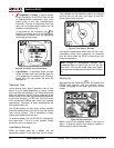
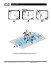
Inductive Clamp Mode: The transmitter is
connected to an inductive clamp which is then closed
around a pipe or cable. The transmitter energizes the
clamp, which then induces a current in the conductor.
Important: Make sure the SR-60 is set to trace mode
and set to the same frequency as the transmitter. Do
not clamp onto a live conductor. This mode works
best when both ends of the conductor are grounded.
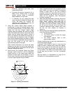
Inductive Mode: The transmitter is placed over
the
conductor. There is no direct connection; the internal
coils of the transmitter generate a strong field through
the ground which induces a current in the
underground conductor of interest. Important: If the
transmitter is too close to the SR-60 in this mode, it
can cause “air-coupling” which means the locator is
reading more on the signal from the transmitter’s
field, than on the target conductor. (See page 16).
Note: When using Inductive Mode, it is always
possible to move the transmitter to a different point
along the target line. This will sometimes improve the
circuit and provide a better signal.
WARNING
Connect ground and power leads of the
transmitter before powering the transmitter on,
to avoid electric shock. See warning on page 4.
1. Energize the target conductor according to
the transmitter manufacturer’s instructions,
using one of the methods described above.
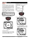
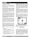
Select the transmitter frequency. Set the
frequency on the SR-60 to the same
frequency used on the transmitter, using the
Frequency Key
. Be sure the frequency has a
line trace icon
. Push the Menu Key to
return to the operating screen. To activate
frequencies not yet made active, see “Frequency
Selection Control” on page
33.
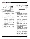
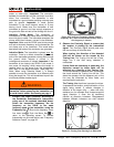
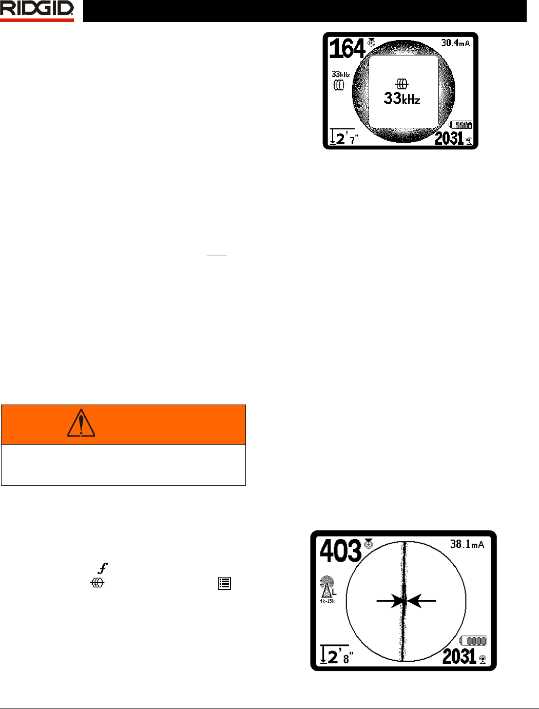
Figure 20: Line Trace Frequency Chosen with the
Frequency Key (This screen will flash briefly when a
new frequency is chosen.)
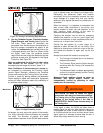
2. Observe the Proximity Signal to ensure that
the receiver is picking up the transmitted
signal. The Proximity Signal should peak over
the line and drop off on either side.
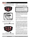
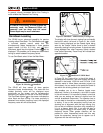
When tracing, the direction of the detected
field will be shown on the screen by the
Tracing Line. The Tracing Line will be a clear,
single line if the field being detected is
undistorted.
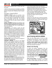
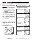
If other fields are interfering in some way, the
distortion caused by those fields will be
reflected by a blurring of the Tracing Line.
The more distorted the detected field, the broader
the cloud around the Tracing Line will be. This
alerts the operator that the apparent axis of the
line may be influenced by other fields, and
requires careful evaluation.
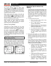
The Tracing Line has three important functions.
It represents the location, and the direction, of the
signal being traced. It reflects changes in
direction of the target utility — when the utility
makes a turn, for example. And it helps recognize
signal distortion. It does this by becoming
cloudier as distortion increases. Disagreement
between different indicators can also indicate
distortion.
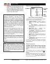
Figure 21: Tracing Line Showing Low Distortion