


Ditch
JS56696,00009E9 1916MAY112/2
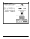
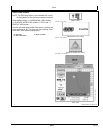
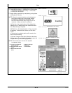
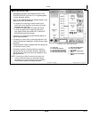
4. Select MENU softkey >> GREENSTAR 3 PRO softkey
>> SURFACE WATER PRO softkey >> DITCH tab
>> PROFILE VIEW button.
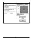
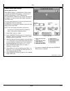
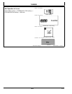
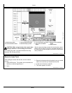
5. Begin ditching operation by manipulating cutting blade
with hydraulic controls.
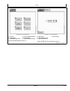
NOTE: If there is a second receiver on the implement,
the system displays the current blade position
by drawing a red profile on the screen. The
blue and optional black drain design line is not
removed, as they are there for reference.
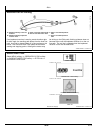
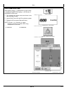
(A) Red line—the actual location of the blade after
making the cut. Ideally the red line follows the black
line when ditching is complete.
(B) Black line—the desired location of the cut created
by pressing "Generate Drain" button on Edit Drain
screen.
(C) Blue line—the existing drain profile saved at the
time of track recording.
(D) Green Triangle—lower point references the blade
of the scraper. As you raise and lower the scraper, this
triangle moves up and down appropriately.
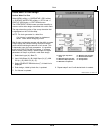
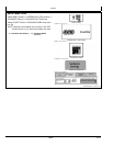
NOTE: Zoom levels and view can be adjusted
for optimal cutting.
A—Location of Blade after
making Cut (red)
B—Desired Location of Cut
(black)
C—Drain Profile Recorded
(blue)
D—Blade of Scraper
E—Ditch tab
F—View button
PC8663 —UN—05AUG05
MENU softkey
PC12685 —UN—14JUL10
GREENSTAR 3 PRO softkey
PC10379 —UN—14OCT07
SURFACE WATER PRO softkey
PC10857BS —UN—15JUL08
Ditch tab
PC13739—UN—16MAY11
4011
061611
PN=43