


Machine and Implement Setup
Continuedon nextpage JS56696,00009D61911MAY111/4
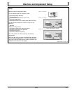
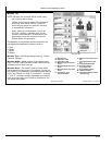
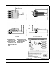
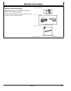
Implement Offsets
Select MENU softkey >> GREENSTAR 3 PRO softkey >>
EQUIPMENT softkey >> IMPLEMENT tab >> CHANGE
OFFSETS button.
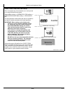
IMPORTANT: Distance (D) is measured when the
implement is in theFULLY RAISED position. This
dimension is critical for accurate ditch designs.
Remember: Always measure to the same
place on the receiver when measuring (that
is, top, middle, and others).
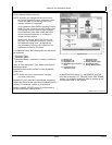
Implement Offsets—Used to define the actual implement
position relative to the tractor. This is important for
ensuring the implement is lined up to the field at the end
of turns and in determining where the implement is for
the Minimize Skips and Minimize Overlaps feature (see
Change Settings on Machine tab).
•
A) Inline distance from connection point to front of
implement. On pulltype implements, think of this as the
tongue. For more precision, it is actually the dimension
from the pinbolt to the front side of where the work gets
done (front ranks of field cultivator, seed drop point on a
planter).
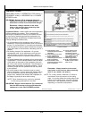
•
B) Working Length of the implement. On ground
engagement tools, this is the distance from the front
rank of sweeps or points to the rear rank. Refer to
implement manufacturer’s Operator’s Manual for this
value.
•
C) Lateral distance from connection point to control point
of implement. This is the lateral distance from the center
of the tractor to the center of the implement which will
be 0.0 for most common implements. This dimension is
used to alert the operator to potential collisions. This is
critical for proper endturn performance and may need
to be adjusted.
•
D) Inline distance from connection point to control
point of implement. In many cases, this distance will be
from the connection point to the carrying wheels. For
proper turns, measure this distance with implement at
the height it typically will be at while turning.
NOTE: These dimensions may need to be adjusted
for finetuning performance in the field.
IMPORTANT: Ensure vertical distance (D) is measured
from the GPS receiver to the ground when the
implement is in the FULLY RAISED position.
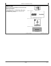
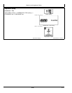
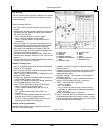
PC11405 —UN—15OCT08
Implement Offsets
A—Inline distance from
connection point to front of
implement.
B—Inline distance from front
to rear of implement.
C—Lateral distance from
connection point to control
point of implement.
D—Inline distance from
connection point to control
point of implement.
E—Inline distance from
connection point to
connection point for
second implement. Value
only needed if second
implement is used.
F—Offset Toggle button
G—A+B = Documentation /
Swath Control location
when in use.
Remember: Always measure to the exact
same place on the receiver when measuring
(that is, top, middle, and others.).
NOTE: For a rotary ditcher, dimension (C) refers to
the distance from the receiver to the cutting
edge. On a rotary ditcher the cutting edge is the
bottom of the paddle wheel, since this contacts
the soil first. This dimension could be adjusted
depending on individual requirements.
158
061611
PN=16